EPSON Stylus C82 Revision A
APPENDIX Connector Summary 52
7.1 Connector Summary
7.1.1 Major Component Unit
The Major component units of this printer are as follows.
Main Board (C486 MAIN)
Power Supply Board (C486 PSB/PSE)
Panel Board (C486 PANEL)
See the following tables for the connector summary for the C486 MAIN Board and
each connector’s pin assignment.
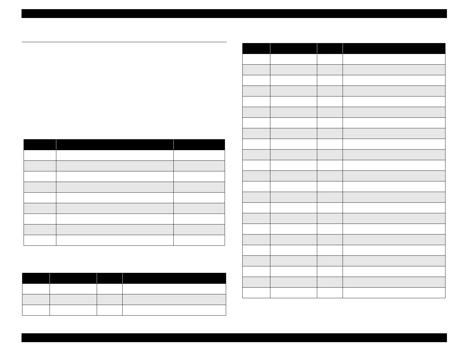
Table 7-1. Connector Summary for C486 MAIN
Connector Function Ref.
CN1 For connection with the Parallel Interface -
CN3 For connection with the USB -
CN4 For connection with the PE sensor Table 7-2
CN8, CN9 For connection with the Printhead Table 7-3, Table 7-4
CN12 For connection with the PF encoder Table 7-5
CN13 For connection with the PF motor Table 7-6
CN14 For connection with the CR motor Table 7-7
CN19 For connection with the Power supply board Table 7-8
CN20 For connection with the Panel board Table 7-9
Table 7-2. CN4 - PE sensor
Pin Signal Name I/O Function
1 PE In Sensor detect signal
2 GND - Ground
3 PEV - Sensor power supply
Table 7-3. CN8 - Printhead
Pin Signal Name I/O Function
1 GND - Ground
2 COM Out Head drive pulse (trapezoid waveform)
3 VBS Out Power for nozzle selector IC
4 COM Out Head drive pulse (trapezoid waveform)
5 VBS Out Power for nozzle selector IC
6 COM Out Ground
7 VBS Out Power for nozzle selector IC
8 COM Out Head drive pulse (trapezoid waveform)
9 GND - Ground
10 GND - Ground
11 TH In Thermistor detect signal
12 VCC3.3 Out Logic power supply (+3.3V)
13 GND - Ground
14 NC - Not connected
15 GND - Ground
16 ENCA In Encoder feed back signal ch.A
17 EVDD Out Power for CR encoder
18 ENCB In Encoder feed back signal ch.B
19 GND - Ground
20 CRST Out Reset signal for address counter of CSIC
21 GND - Ground
22 CSCK IN/Out Clock signal for CSIC read/write
23 CVDD Out Power for CSIC memory
 Loading...


