WF-2540 / WF-2530 / WF-2520 / WF-2510 / WF-2010 series Revision B
Disassembly/Reassembly Detailed Disassembly/Reassembly Procedure for each Part/Unit 44
Confidential
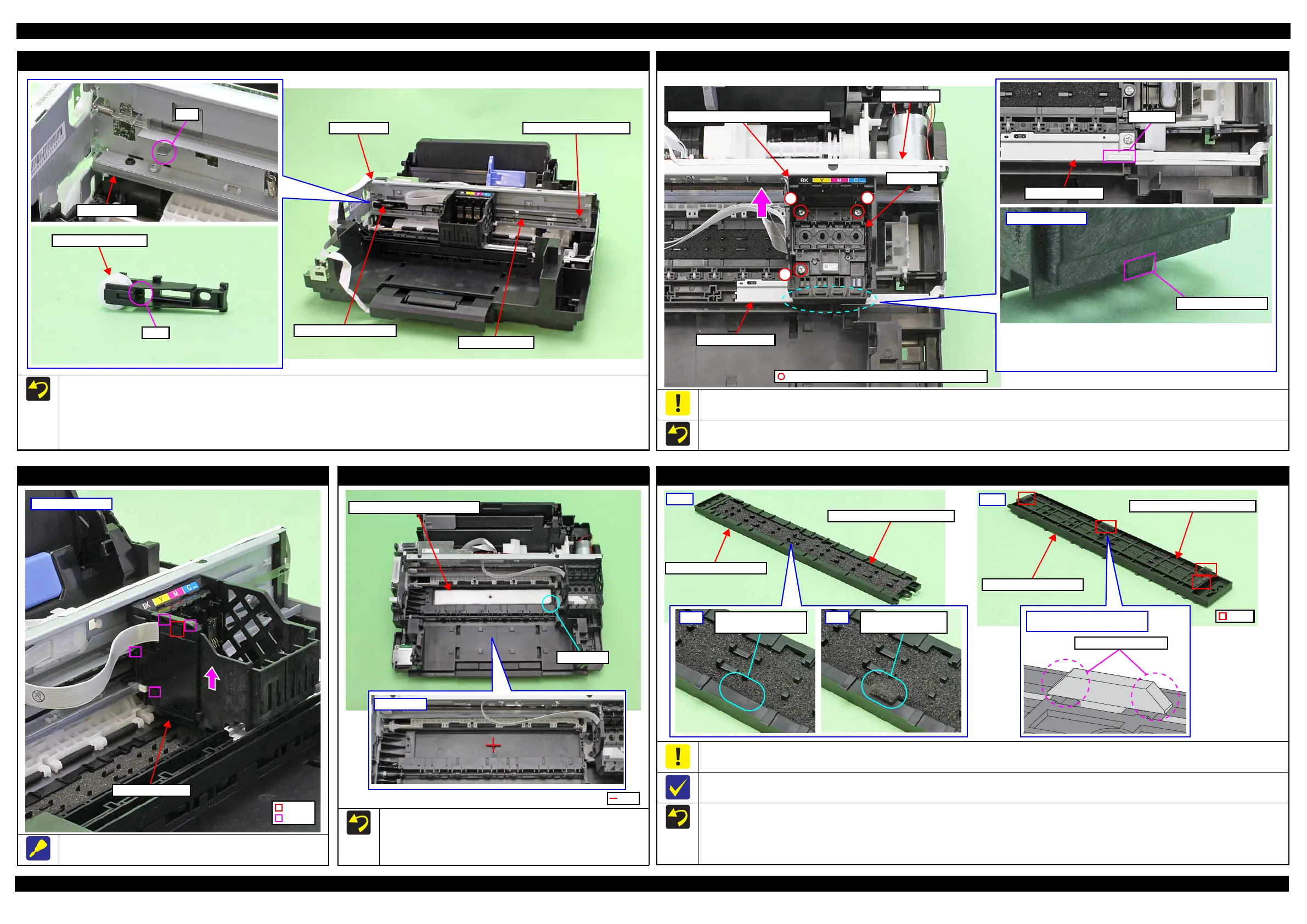
CR Driven Pulley Assy / CR Timing Belt
When installing the CR Driven Pulley Assy and CR Timing Belt, follow the procedure below.
1. Install the CR Driven Pulley Assy to the Main Frame.
2. Attach the Compression Spring 20.91 in the order from the dowel on the CR Driven Pulley Assy to the rib on the Main Frame.
3. Attach the CR Timing Belt to the CR Driven Pulley Assy.
4. Attach the CR Timing Belt on the pinion gear of the CR Motor while pushing the CR Driven Pulley Assy to the 0-digit side.
CR Driven Pulley Assy
Dowel
Main Frame
CR Timing Belt
Pinion gear of CR Motor
Compression Spring 20.91
Printhead
When removing/replacing the Printhead, be sure the CR Unit is at the “ink cartridge exchange position” shown above. Otherwise, the Main Frame
may be deformed by applying force perpendicularly when tightening the screws and it may affect print quality.
Tighten the screws of the Printhead in the order indicated in the figure above while pressing the Printhead in the direction of the arrow.
1
2
3
Ink cartridge exchange position: when the protrusion of the CR Unit is
on the protrusion of the PIS Shield Plate A.
Do not remove/replace the Printhead other than under this condition in
order to prevent the Main Frame from being deformed.
Protrusion of CR Unit
Bottom of CR Unit
PIS Shield Plate A
Protrusion
PIS Shield Plate A
Main Frame
Printhead
CR Unit (ink cartridge exchange position)
C.B.P-TITE SCREW 2.5x8 F/ZN-3C (5 ± 0.5 kgf·cm)
FFC Cover Outer
Slide and remove the FFC Cover Outer in the direction of the arrow
while releasing the hook.
FFC Cover Outer
Left side of CR Unit
Hook
Rib
Paper Guide Lower Porous Pad
When installing the Paper Guide Lower Porous Pad, set it with
the cut section to the front right of the printer.
Align the cutout of the Paper Guide Lower Porous Pad with the
rib of the Frame Base.
Paper Guide Lower Porous Pad
Paper Guide Front Porous Pad
When installing the Paper Guide Front Porous Pad, make sure to wipe off the grease attached on the Paper Guide Front Unit.
The Paper Guide Front Porous Pad is not included in the replacement parts when the maintenance error occurs.
The shapes of the Paper Guide Front Unit and Paper Guide Front Porous Pad differ between models because of the size of the borderless printing.
After installing the Paper Guide Front Porous Pad, make sure of the following.
The entire anti-disconnect hooks on both ends of the legs of the Paper Guide Porous Pad should come out from the holes on the bottom of the
Paper Guide Front Unit.
The tabs of the Paper Guide Front Porous Pad should be inserted completely into the grooves of the Paper Guide Front Unit.
No parts of the Paper Guide Porous Pad are wavy or lift over the platen surface of the Paper Guide Front Unit.
Back
Paper Guide Front Unit
Paper Guide Front Porous Pad
Leg
Front
Paper Guide Front Porous Pad
Paper Guide Front Unit
No tab of the pad sticks
out on the frame.
OK
A tab of the pad sticks
out on the frame.
NG
Enlarged figure: a leg of Paper
Guide Front Porous Pad
Anti-disconnect hooks