WF-2540 / WF-2530 / WF-2520 / WF-2510 / WF-2010 series Revision B
Disassembly/Reassembly Detailed Disassembly/Reassembly Procedure for each Part/Unit 45
Confidential
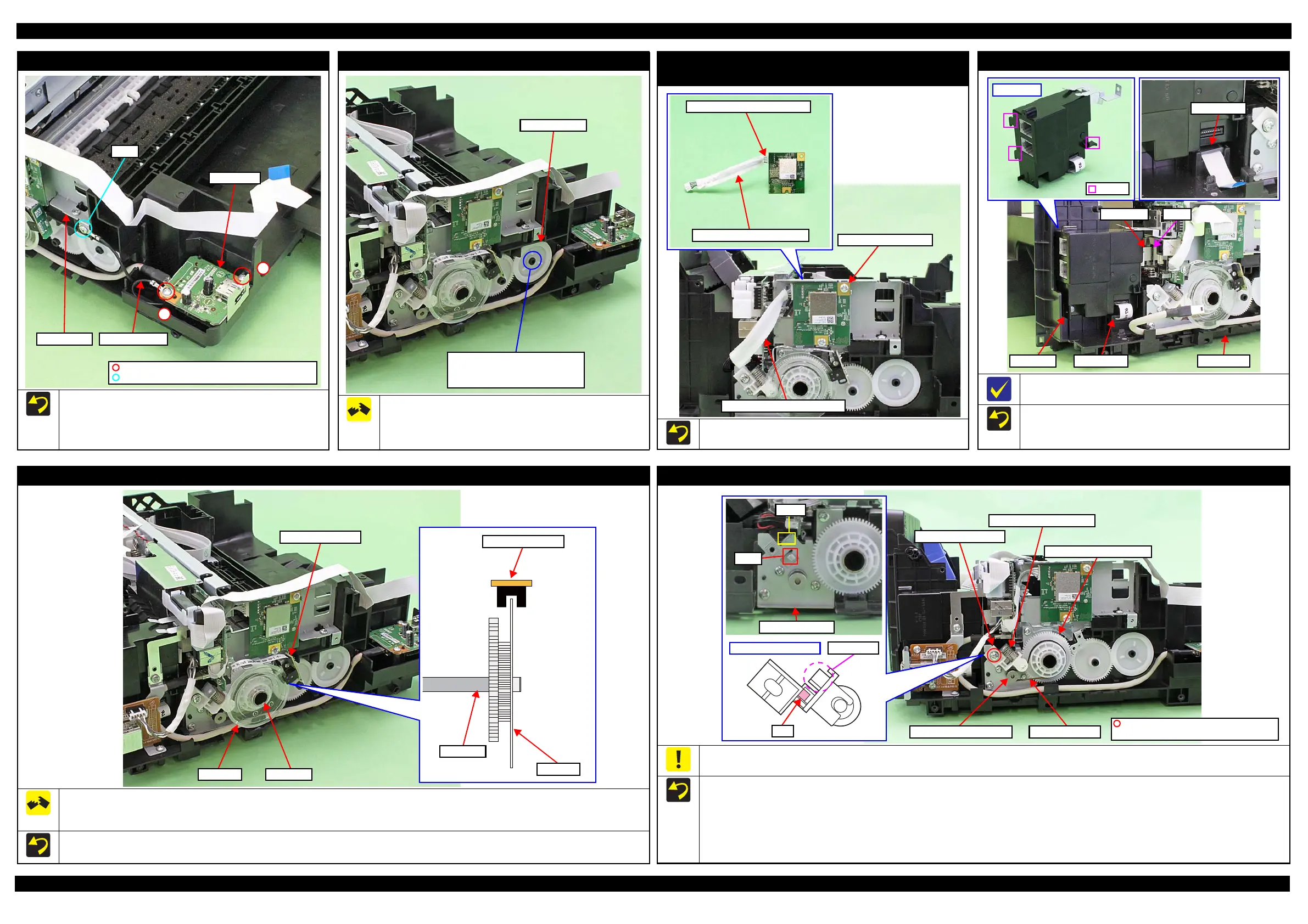
USB Board (USB compatible model)
Tighten grounding wire together on the position indicated in
the figure above.
Install the grounding wire terminal on the Main Frame side on
the direction indicated in the figure above.
Tighten the screws in the order indicated in the figure above.
USB Board
C.B.P-TITE SCREW 3x10 F/ZN-3C (6 ± 1 kgf·cm)
C.B.S-TITE SCREW 3x6 F/ZN-3C (6 ± 1 kgf·cm)
Joint
Main Frame Grounding wire
1
2
EJ Roller Gear
The rib on the contact point of the EJ Roller Gear with the EJ
Roller is deformed when removing the EJ Roller Gear. Therefore,
make sure to replace it with a new one when removing it in order to
maintain the paper feed accuracy.
Can not be reused because the rib
of the EJ Roller Gear is deformed
once removed from the EJ Roller.
EJ Roller Gear
Wireless LAN Module
(Model with wireless LAN)
Attach two pieces of acetate tape on the Wireless LAN Module
cable to cover the cable to protect it as shown above.
Wireless LAN Module
Wireless LAN Module Cable
Wireless LAN Module Cable
Cover with acetate tape (x2).
FAX Assy (Models with FAX)
Connect the FAX FFC to the connector (CN1) of the Main Board
before installing the FAX Assy.
Install the hook (x3) of the FAX Assy on the Frame Base.
Put the ferrite core on the position indicated in the figure
above.
CN1FAX FFC
Frame BaseFAX Assy
PF Encoder Sensor / PF Scale
Do not reuse the removed PF Scale and make sure to replace it with a new one when removing it.
When installing the PF Scale, it is pressed into the PF Roller, therefore, the removed one is deformed. If it is re-installed to the printer, it does not
rotate properly and the paper feed accuracy may be reduced.
When installing the PF Scale to the PF Roller, press the PF Scale into the PF Roller vertically.
After installing the PF Encoder Sensor, confirm the PF Scale does not touch the PF Encoder Sensor.
PF Encoder Sensor
PF Scale
PF Roller
PF Scale
PF Encoder Sensor
PF Roller
PF Driven Pulley Assy / PF Timing Belt
Do not hold the PF Driven Pulley Assy when securing it with the screw in order to prevent applying improper tension to the PF Timing Belt.
When installing the PF Driven Pulley Assy, follow the procedure below.
1. Align the rib of the PF Driven Pulley Assy with the hook of the PF Motor Frame, and install the PF Driven Pulley Assy.
2. Attach the Compression Spring 5.07 to the protrusion of the PF Driven Pulley Assy and the dowel of the PF Motor Frame.
3. Attach the PF Timing Belt in the order of the pinion gear of the PF Motor, PF Driven Pulley and Combination Gear 29.2,42.
4. Rotate the Combination Gear 29.2,42 clockwise three times to confirm the PF Timing Belt is correctly attached, and then secure the PF Driven
Pulley Assy with the screw and washer to the PF Motor Frame.
Protrusion
Rib
PF Driven Pulley Assy
C.B.S-TITE(P2) SCREW 3x6 F/ZN-3C
P.W. 3.4x0.43x7 (7 ± 1 kgf·cm)
Pinion gear of PF Motor PF Timing Belt
Compression Spring 5.07
PF Driven Pulley Assy
Combination Gear 29.2,42