WF-2540 / WF-2530 / WF-2520 / WF-2510 / WF-2010 series Revision B
Disassembly/Reassembly Routing FFCs/cables 49
Confidential
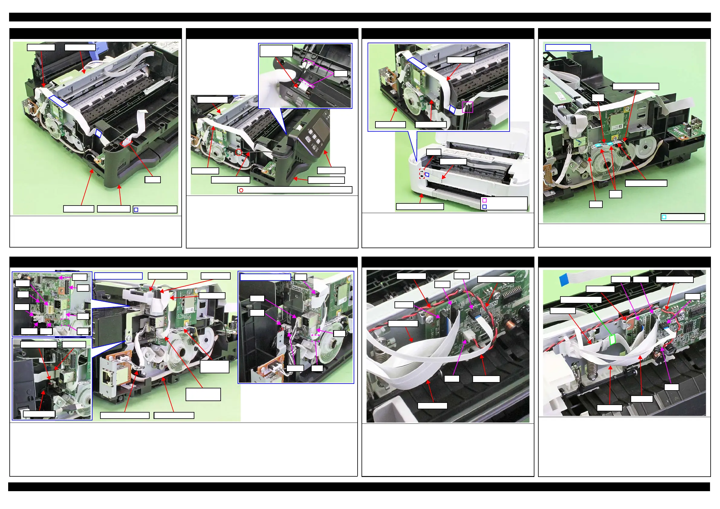
Panel FFC (Multifunction Printer)
Route the Frame Base and Main Frame along the folded line and secure
with the double-sided tape on the position shown in the above.
After installing the Housing Front, route the Panel FFC through the hole
of the Housing Front.
Housing Front
Main FramePanel FFC
Frame Base
Hole
Double-sided tape
Panel Unit (Multifunction Printer)
Route the Panel FFC and grounding wire as follows before installing the
Panel Unit.
• Route the Panel FFC through the hole of the Panel Unit and connect the
connector of the Panel Board.
• Route the grounding wire through the hole of the Housing Front.
After installing the Panel Unit, secure the grounding wire to the Main
Frame on the position indicated in the figure above with screw (x1).
Hole
Connector of
Panel Board
Main Frame
Panel FFC
Grounding wire
Housing Front
Panel Unit
C.B.S-TITE SCREW 3x6 F/ZN-3C (6 ± 1 kgf·cm)
Panel FFC (Singlefunction Printer)
Route the Panel FFC through the rib of the Frame Base and Main Frame
along the folded line and secure with the double-sided tape on the position
shown above.
Route through the hole of the Housing Upper Assy and secure with the
double-sided tape on the position shown above.
Panel FFC
Frame Base Main Frame
Housing Upper Assy
Panel FFC
Hole
PF Encoder Sensor
Route the PF Encoder through ribs of the Main Frame and connect the
connector (CN7) of the Main Board. Then secure with the double-sided tape
(x2) on the position shown in above.
Left side of printer
PF Encoder Sensor
PF Encoder FFC
Rib
Double Side Tape
CN7
Ribs
Left side of Main Board
Connect the following cables/FFCs to the Main Board as shown above.
• PF Motor cable (CN13) • PS Unit cable (CN501)
• Wireless LAN Module Cable (CN4: only for Wireless LAN compatible model) • PF Encoder FFC (CN7)
• USB Board cable (CN9: only for USB compatible model) • FAX FFC (CN1: only for FAX compatible model)
• Ethernet Board cable (CN14: only for Ethernet compatible model)
• Panel FFC (CN2) : Secure the ferrite core of the FFC Holder MB and connect to the Main Board through the ferrite core.
(Singlefunction Printer has no FFC Holder MB and ferrite core.)
CN11
CN2
CN9
CN4
CN7
CN13
CN501
CN1
CN14
Wireless LAN
Module Cable
FFC Holder MB Ferrite core
Panel FFC
PF Encoder
FFC
Singlefunction Printer
CN14
CN13
CN2
CN4
CN7CN501
USB Board cable
Multifunction Printer
PF Motor cable FAX FFC
PS Unit cable
Right side of Main Board (Multifunction Printer)
Connect the following cables/FFCs to the Main Board as shown in the figure
above.
• CR Motor cable (CN12)
• CSIC FFC (CN6)
• Head FFC (CN102)
• PIS FFC (CN23)
Route the PIS FFC over the Head FFC and CSIC FFC.
Main Board
CN12
CN102
Head FFC
CSIC FFC
CN61
CR Motor cable
CN23
PIS FFC
Right side of Main Board (Singlefunction Printer)
Connect the following cables/FFCs to the Main Board as shown in the figure
above.
• CR Motor cable (CN12)
• CSIC FFC (CN6)
• Head FFC (CN102)
Secure with the double-sided tape on the position shown above.
• PIS FFC (CN23)
Route the upper side of the Head FFC and CSIC FFC.
Main Board
CN12
CN102
Head FFC
CSIC FFC
CN61 CR Motor cable
CN23
PIS FFC
Double-sided tape