WF-2540 / WF-2530 / WF-2520 / WF-2510 / WF-2010 series Revision B
Disassembly/Reassembly Routing FFCs/cables 50
Confidential
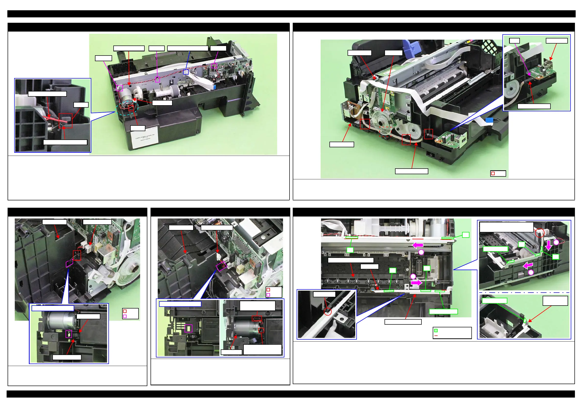
CR Motor
Route the CR Motor cable as follows before installing the Shield Plate.
1. Route the CR Motor cable (black) around the rib A of the Frame Base (two turns).
2. Route the CR Motor cable (red) through the rib B of the Frame Base, and then route it through the rib A taking care not to let the CR Motor cable (red)
come over the CR Motor cable (black).
3. Twist the CR Motor cable (black) and CR Motor cable (red) twice, and then route them through the hook C of the Main Frame.
4. Route the CR Motor cable (black) and CR Motor cable (red) in the order of hook D of the Main Frame, groove of the FFC Holder, and hook E of the Main
Frame.
CR Motor cable (red)
Rib A
CR Motor cable (black)
Hook C
Rib B
CR Motor
Hook EGroove of FFC HolderCR Motor cable Hook D
USB Board (USB compatible model)
When routing the USB Board cable, be careful not to damage the PF Scale.
Route the USB Board cable through the ribs (x4) of the Frame Base.
Connect the connectors on both ends of the USB Board cable to the Card Slot Board (CN3) and Main Board (CN9) firmly. (p 49)
Frame Base
Main Board PF Scale
Rib
USB BoardCN2
USB Board cable
PS Unit
Pull out the PS Unit cable from the hole of the Frame Base first, and then
route it through the rib of the Frame Base.
Put the ferrite core into the position shown in the figure above.
Bottom of Frame Base
PS Unit cable
Ferrite core
PS Unit cableFrame Base
Hole
Rib
PF Motor
Route the PF Motor cable as follows.
1. Pull out the PF Motor cable from the hole of the Frame Base.
2. Install the PF Motor, and secure the PF Motor cable (black) with the rib of
the Frame Base, and then route it through the rib of the Frame Base.
PF Motor
Route PF Motor
cable through rib.
Secure PF Motor
cable (black) with rib.
PF Motor cable
Hole
Rib
Frame Base
PIS FFC
Route the PIS FFC/cable as follows
1. Align the PIS FFC to the standard line on the PIS Shield Plate B, and route it in the direction of arrow (1) taking care not to let it cover the protrusion of the
Star Wheel Holder Assy, then secure the FFC with double sided tape in the order from A to C shown above.
2. Align the fold on the PIS FFC with the corner of the Frame Base, and route the FFC along the standard line on the Main Frame in the direction of arrow (2),
then secure the FFC with double sided tape in the order of D and E shown above.
3. From the fold on the PIS FFC aligned in Step 2, route the FFC in the direction of arrow (3), and secure it with double sided tape at F shown above.
4. Route the PIS FFC in the direction of arrow (4), and secure it with double sided tape in the order of G and H shown above.
3
4
H: Fold back
Align the fold on PIS FFC with
the corner of Frame Base
G
F
PIS Shield
Plate B
H: Fold back
1
2
PIS FFC
Star Wheel Holder Assy
PIS Shield Plate B
A
B
E
D
C: 20 x 4 mm
Standard line
Double-sided tape