Epson WF-5690/4640/4630/5620/5190/5110series Revision D
Disassembly/Reassembly Detailed Disassembly/Reassembly Procedure for each Part/Unit 39
Confidential
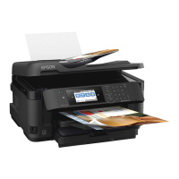
Panel Assy (WF-5690/4640/4630/5620 series)
When removing the Panel Assy, follow the procedure below.
1. Open the Front Cover, and release the hook A (x2) of the Panel Assy from the bottom of the Scanner Unit.
2. Release the hook B (x5) of the Panel Assy.
3. Lift the Panel Assy in the direction of the arrow and release the ribs (x5) and hook C (x2) on the top of the Panel Assy, and then remove the Panel
Assy.
Back of Panel Assy
Panel Assy
Bottom left of Scanner Unit
Scanner
Unit
Scanner
Unit
Bottom right of Scanner Unit
Panel Assy
Scanner
Unit
Front
Cover
Hook C
Rib
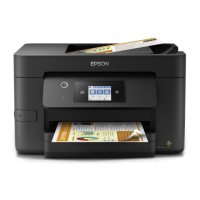
Panel Assy (WF-5190/5110 series)
When removing the Panel Assy, follow the procedure below.
1. Open the Front Cover, and release the hook A of the Panel Assy from the bottom of the Housing Upper Assy.
2. Release the hook B (x5) and rib A (x3) of the Panel Assy.
3. Slide the Panel Assy slightly in the direction of the arrow and release the rib B (x2), and remove the Panel Assy.
Panel Assy
Bottom of Panel Assy
Bottom of Housing Upper Assy
Housing Upper Assy
Hook A
Hook B
Rib A
Rib B
Housing Upper Assy
Front
Cover
Panel Assy
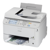
Main Board Unit
When installing the Main Board Unit, insert the ribs of the Main Board Unit Bracket Front/Main Board Unit Bracket Rear into the holes of the
Main Board Unit.
After installing the Main Board Unit, make sure the legs of the Main Board Unit Grounding Plate touch the Main Frame.
Main
Board Unit
Legs
Left
Main Frame
Rib and hole
C.B.S-TITE SCREW 3x6 F/ZN-3C (6 ± 1 kgf·cm)
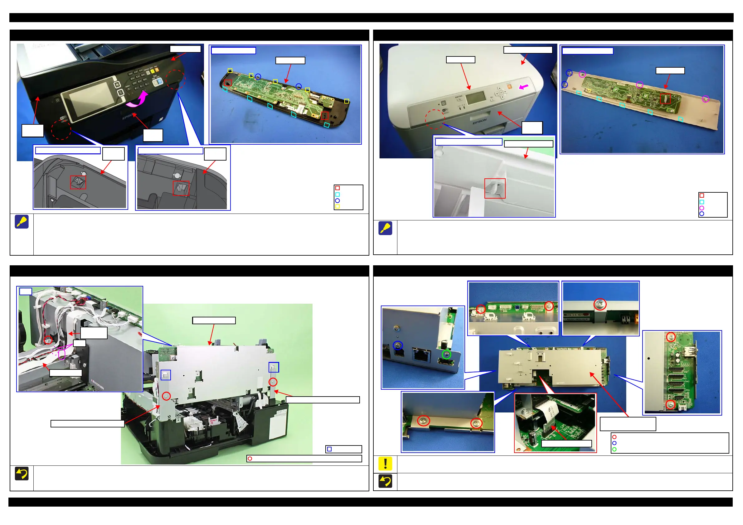
Main Board Unit
Main Board Unit Bracket Front
Main Board Unit Bracket Rear
Main Board Shield Plate Upper Assy
The Interface Board FFC is connected to the back of the Main Board Shield Plate Upper Assy, therefore, be careful of it when removing the Main
Board Shield Plate Upper Assy.
The above figure shows the kind and the position of the screw.
C.P.SCREW 3x4 F/ZN-3C (6 ± 1 kgf·cm)
C.P.SCREW 2.5x6 F/ZN-3C (6 ± 1 kgf·cm)
C.B.S-TITE-SCREW 3x6 F/ZN-3C (6 ± 1 kgf·cm)
Main Board Shield Plate
Upper Assy
 Loading...