Epson WF-5690/4640/4630/5620/5190/5110series Revision D
Disassembly/Reassembly Detailed Disassembly/Reassembly Procedure for each Part/Unit 40
Confidential
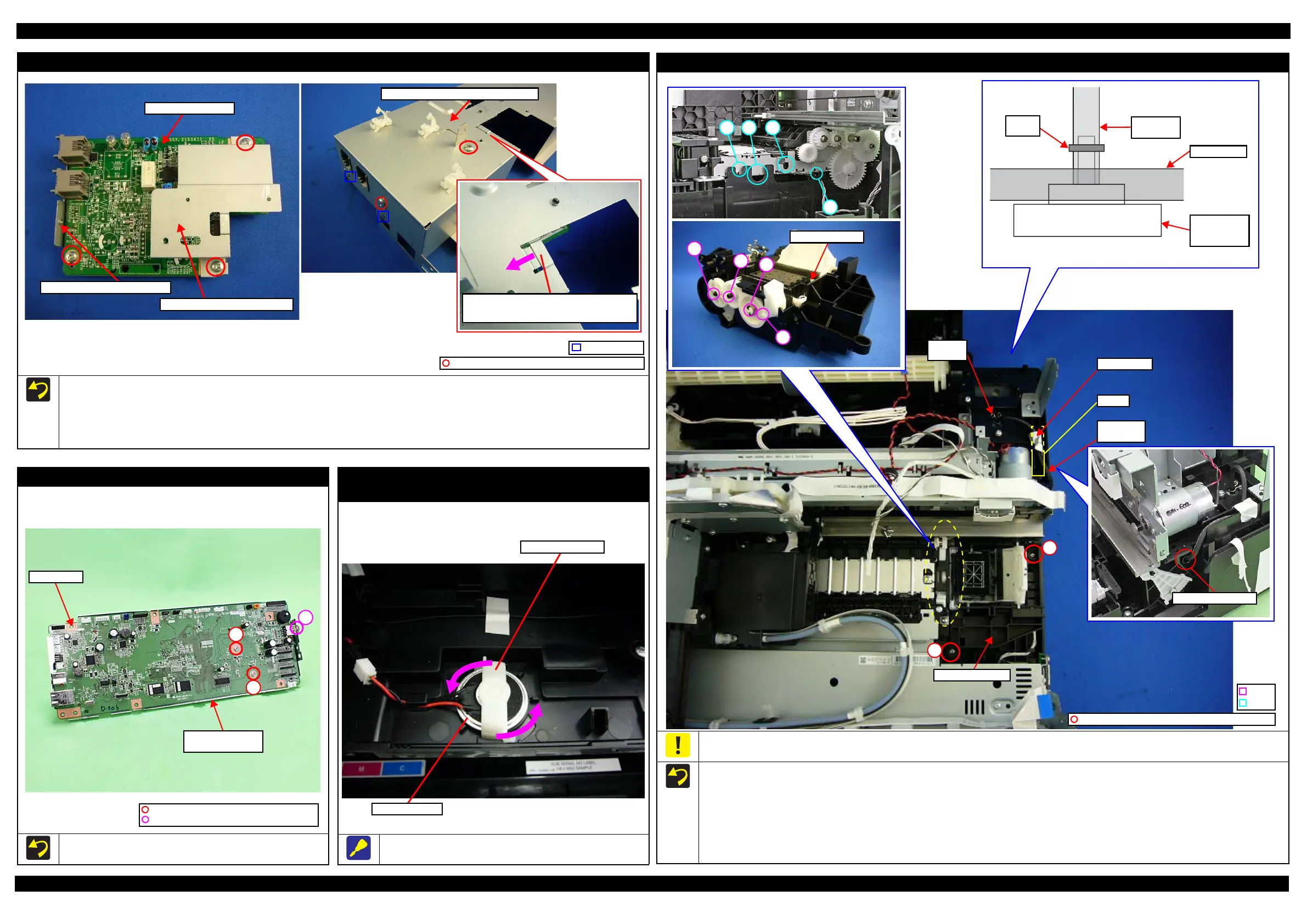
Interface Board Assy (WF-5690/4640/4630/5620 series)
When removing the Interface Board Assy, follow the procedure below.
1. Interface Board Shield Plate, Interface Board, Interface Board Grounding Plate are secured with the screws (x3).
2. Aline the dowel of the Main Board Shield Plate with the hole of the Interface Board Assy, and install the Main Board Shield Plate to the Interface
Board Assy.
3. The above figure shows the kind and position of the screw.
Main Board Shield Plate Upper Assy
Interface Board Shield Plate
Interface Board Grounding Plate
Interface Board
Slide the Interface Board Assy, and install it
to the Main Board Shield Plate Upper Assy.
C.B.S-TITE SCREW 3x6 F/ZN-3C (6 ± 1 kgf·cm)
Dowel and hole
Main Board / Main Board Shield Plate Lower Assy
Tighten the screws in the order indicated in the figure above.
2
1
C.P.SCREW 2.5x6 F/ZN-3C (2 ± 5 kgf·cm)
Main Board
Main Board Shield
Plate Lower Assy
C.P.SCREW 3x6 F/ZN-3C (6 ± 1 kgf·cm)
3
Speaker/Speaker Holder
(WF-5690/4640/4630/5620 series)
Spin the Speaker Holder in the direction of the arrow of the above
figure, and remove the Speaker and Speaker Holder.
Ink System Unit
When connecting the Ink System Tube to the Maintenance Box Ink Eject Joint, make sure to insert the end of the tube into the socket on the
Maintenance Box Ink Eject Joint up to the full to its base in order to prevent the waste ink from leaking.
When installing the Ink System Unit, follow the procedure below.
1. Route the Ink System Tube through the hole of the Frame Base.
2. Align the dowels A to dowel E of the Ink System Unit with the hole A to hole E of the Frame Base, and install the Ink System Unit to the Frame Base.
3. Insert the end of the Ink System Tube into the socket on the Maintenance Box Ink Eject Joint to the full up to its base, and secure the tube with
the tube clamp.
4. Route the Ink System Tube through the groove of the Frame Base, and secure it with acetate tape.
5. Tighten the screws (x2) in the order indicated in the figure above to secure the Ink System Unit to the Frame Base.
Ink System Unit
1
2
Dowel
Hole
Maintenance
Box Ink Eject
Joint
Frame Base
Ink System
Tube
Tube
clamp
C.B.P-TITE SCREW 3x10 F/ZN-3C (6 ± 1 kgf·cm)
Groove
Acetate tape
Ink System
Tube
Tube
clamp
 Loading...