Epson WF-5690/4640/4630/5620/5190/5110series Revision D
Disassembly/Reassembly Detailed Disassembly/Reassembly Procedure for each Part/Unit 43
Confidential
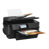
Rear ASF Assy
When installing the Rear ASF Assy to the Frame Base Assy,
move the Trigger Lever in the direction of the arrow to prevent
it from touching the Clutch Lever, and align the positioning
holes (x2) of the Rear ASF Assy with the dowels (x2) of the
Frame Base Assy.
Tighten the screws in the order indicated in the figure above.
Frame Base
Assy
Dowel and
positioning hole
C.B.P-TITE SCREW 3x10 F/ZN-3C (6 ± 1 kgf·cm)
Trigger Lever Clutch Lever
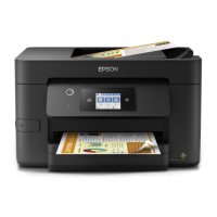
Rear ASF Guide Upper Assy
When installing the Rear ASF Guide Upper Assy, follow the
procedure below.
1. Insert the ribs (x2) on the 80-digit side of the Rear ASF Guide
Upper Assy into the holes (x2) of the Frame Driven Assy.
2. Align the positioning hole on the 0-digit side of the Rear ASF
Guide Upper Assy with the dowel of the Frame Base Assy, and
secure the Rear ASF Guide Upper Assy with the screw.
C.B.P-TITE SCREW 3x10 F/ZN-3C (6 ± 1 kgf·cm)
Rib
Dowel and
positioning hole
Rear ASF Guide Upper Assy
Rear ASF Guide Upper Assy
Step 1
Step 2
Holes of Frame Driven Assy
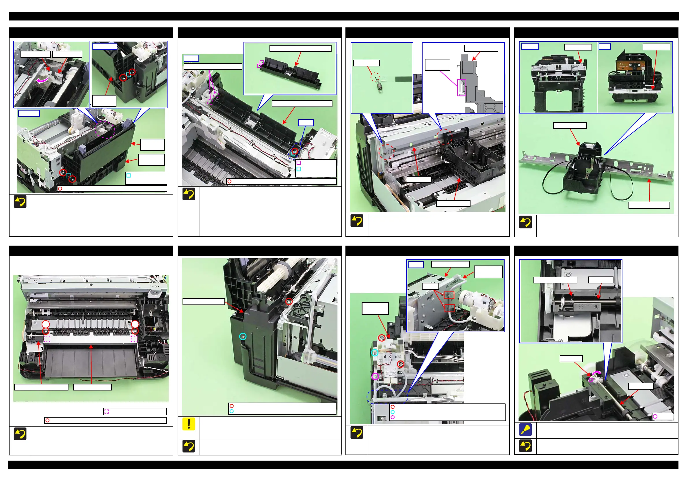
CR Scale
Install the CR Scale with the black mark section up.
Make sure to put the CR Scale through the slit of the CR
Encoder.
Carriage Assy
Slit of CR
Encoder
Carriage Assy
Before installing the Carriage Assy to the CR Guide Frame, make
sure the APG Slider is correctly installed to the Carriage Assy as
shown above.
Carriage Assy
CR Guide Frame
Star Wheel Assy
When installing the Star Wheel Assy, align the positioning holes
(x2) on the bottom of the Star Wheel Assy with the dowels (x2) of
the Paper Guide Front Assy, and tighten the screws (x2) in the
order indicated in the figure above.
1
2
C.B.P-TITE(S-P1) SCREW 3x12 F/ZN-3C (6 ± 1 kgf·cm)
Paper Guide Front Assy Star Wheel Assy
Dowel and positioning hole
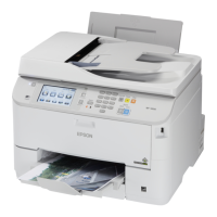
Power Supply Unit
When removing the Power Supply Unit, the Power Supply Unit
cable may touch the Frame. Be careful not to damage the Power
Supply Unit cable then.
The above figure shows the kind and position of screw
C.B.S-TITE SCREW 3x6 F/ZN-3C (6 ± 1 kgf·cm)
C.B.P-TITE SCREW 3x10 F/ZN-3C (6 ± 1 kgf·cm)
Power Supply Unit
Decompress Pump Unit
The above figure shows the kind and position of screw.
Route the Decompress Pump Tube through the hooks (x2) of
the Ink Supply Unit, and insert the end of the tube into the joint
on the Ink Supply Unit to the full up to its base.
C.B.P-TITE(P2) SCREW 3x10 F/ZN-3C (6 ± 1 kgf·cm)
C.B.P-TITE SCREW 3x10 F/ZN-3C (6 ± 1 kgf·cm)
C.B.S-TITE SCREW 3x6 F/ZN-3C (6 ± 1 kgf·cm)
Joint of Ink
Supply Unit
Hooks
Ink Supply Unit
Back
EJ Roller
Release the dowel of the Bush, 5, and detach it from the frame by
rotating it in the direction of the arrow, and then remove the EJ Roller.
Make sure the grounding spring touches the EJ Roller on the
position shown above.
EJ Roller
Grounding spring
 Loading...