Epson WF-5690/4640/4630/5620/5190/5110series Revision D
Disassembly/Reassembly Detailed Disassembly/Reassembly Procedure for each Part/Unit 42
Confidential
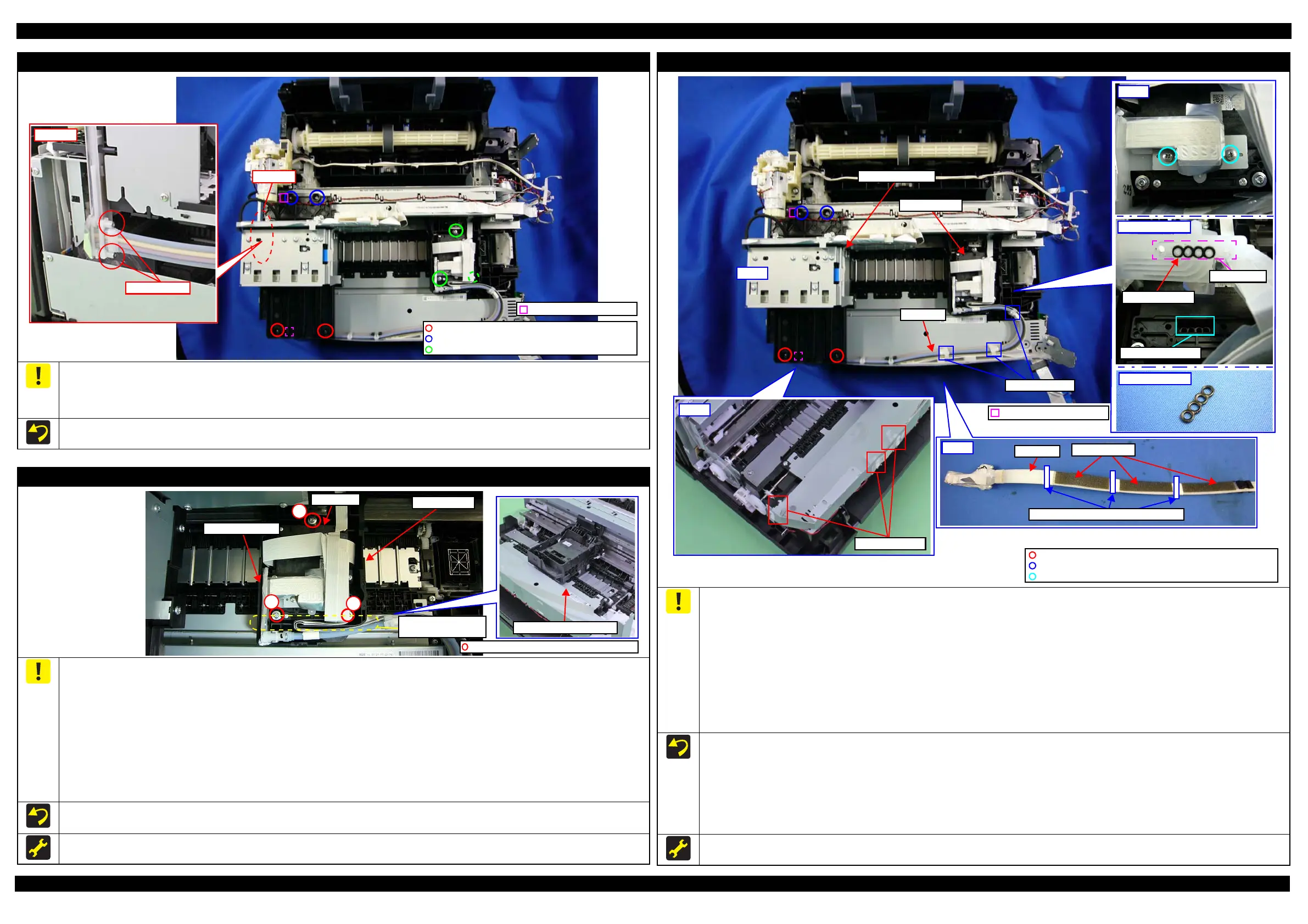
Ink System Supply Assy (Ink Supply Unit w/ Printhead)
When removing/installing the Printhead, move the Carriage Assy to the center of the printer, and place the Spacer (about 5 mm) between the
Carriage Assy and Star Wheel Assy in order to prevent the CR Guide Frame and Main Frame from being deformed. (See " Printhead (p42)".)
To prevent ink leakage, make sure not to separate the ink tubes from the I/C Holder Unit by removing the screws (x2) in section A shown above.
Loosening the screws even just once will cause ink leakage, therefore, make sure to replace the Ink System Supply Assy with a new one.
When installing the Ink System Supply Assy, see " Printhead (p42)" and " Ink Supply Unit (p42)".
P.W.,2.8x0.5x6.5, F/ZN-3C (3 ± 0.5 kgf·cm)
C.B.S-TITE SCREW 3x6 F/ZN-3C (6 ± 1 kgf·cm)
Positioning hole and dowel
Section A
C.B.S-TITE(P2)SCREW 3x8 F/ZB-3C (6 ± 1 kgf·cm)
Printhead
To replace the Printhead, it is necessary to disconnect the joint section of the Printhead and the ink tubes of the Ink Supply Unit. Before
disconnecting the joint section, perform “Ink Pressure Release” in advance. (See "2.2.1 Caution when Replacing the Printhead/Ink Supply Unit
(p27)" and " Ink Supply Unit (p42)".)
When disconnecting the joint section of the ink tubes of the Ink Supply Unit and the Printhead, ink may slightly spill over from the ink tubes
even if “Ink Pressure Release” has been performed. To prevent the inside of the printer being made dirty by the spilling ink, make sure to attach
tape at the joint section of the ink tube when disconnecting the joint section of the ink tube of the Ink Supply Unit and the Printhead.
(See " Ink Supply Unit (p42)".)
When disconnecting the ink tubes from the Printhead, make sure to replace the rubber packing between the ink tubes and the Printhead with a
new one in order to prevent ink leakage.
When removing/installing the Printhead, move the Carriage Assy to the center of the printer, and place the Spacer (about 5 mm) between the
Carriage Assy and Star Wheel Assy in order to prevent the CR Guide Frame and Main Frame from being deformed.
Tighten the screws in the order indicated in the figure above.
After installing the Printhead, make sure to connect the ink tubes to the Printhead. (See " Ink Supply Unit (p42)".)
When replacing the Printhead, make sure to perform "3.2.7 Ink Leak Check (p79)" and
P.W.2.8x0.5x6.5 F/ZN-3C (3 ± 0.5 kgf·cm)
2
3
1
Printhead
Carriage Assy
Star Wheel Assy
Position for Spacer
(5 mm)
Ink Supply Unit
Before disconnecting the joint section of the Printhead and the ink tubes of the Ink Supply Unit, it is necessary to perform “Ink Pressure Release”
in advance. Make sure to perform “Ink Pressure Release”, otherwise, the ink in the ink tube will spill over. (See "2.2.1 Caution when Replacing
the Printhead/Ink Supply Unit (p27)".)
When disconnecting the joint section of the ink tubes of the Ink Supply Unit and the Printhead, ink may slightly spill over from the ink tubes
even if “Ink Pressure Release” has been performed. To prevent the inside of the printer being made dirty by the spilling ink, make sure to attach
tape at the joint section of the ink tube hen disconnecting the joint section of the ink tube of the ink supply unit and the printhead.
(See " Printhead (p42)".)
When disconnecting the ink tubes from the Printhead, make sure to replace the rubber packing between the ink tubes and the Printhead with a
new one in order to prevent ink leakage.
When connecting the ink tubes to the Printhead, place the Spacer (about 5 mm) between the Carriage Assy and Star Wheel Assy in order to
prevent the CR Guide Frame and Main Frame from being deformed. (See " Printhead (p42)".)
When installing the Ink Supply Unit, follow the procedure below.
1. Align the positioning holes (x2) and dowels (x2) shown above, and tighten the screws (x4) of the I/C Holder Unit in the order indicated in the figure above.
2. Secure the ink tubes with the Tube Holder A (x3).
3. Move the Carriage Assy to the center of the printer.
4. While aligning the Tube Holder C attached on the ink tubes with the groove of the Carriage Assy, insert the joint section on the end of the ink
tubes into the holes of the Printhead, and then secure the end of the ink tubes with the screws (x2).
5. Secure the ink tubes with the Tube Holder B (x3), and then adjust their attachment positions to between the Tube Spacers.
Once you loosen the screws on the joint section of the ink tubes to the Printhead, make sure to perform "3.2.7 Ink Leak Check (p79)".
End of ink tube
Rubber packing
Holes of Printhead
Joint section
Positioning hole and dowel
I/C Holder Unit
Ink tube
Tube Spacers
Ink tube
Attachment positions of Tube Holder B
Step 5
Tube Holder B
Carriage Assy
C.B.EP-TITE SCREW,2.6x17(B=14),F/ZN-3C (3 ± 0.5 kgf·cm)
C.B.S-TITE SCREW 3x6 F/ZN-3C (6 ± 1 kgf·cm)
C.B.S-TITE(P2)SCREW 3x8 F/ZB-3C (6 ± 1 kgf·cm)
 Loading...