Epson WF-7620 / WF-7610 / WF-7110 Series Revision B
Disassembly/Reassembly Detailed Disassembly/Reassembly Procedure for each Part/Unit 45
Confidential
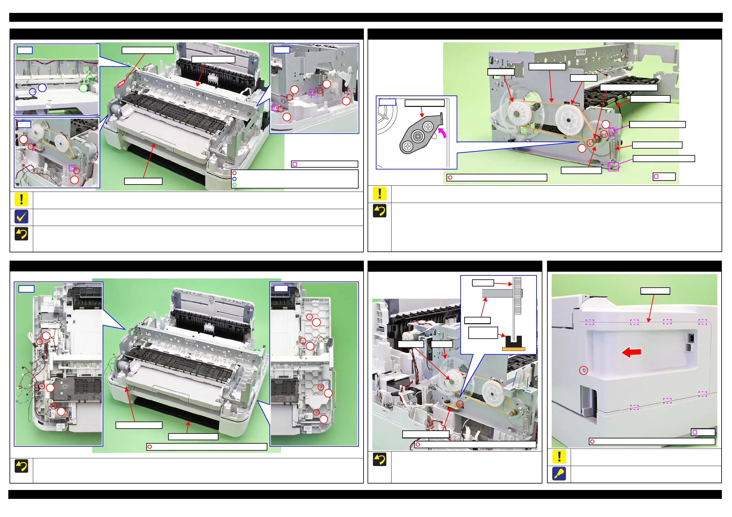
Main Frame Unit
When handling the MAC address label, take care not to damage or contaminate it.
When replacing the Printer Mechanism, remove the MAC address label from the old Printer Mechanism and transfer the label on to the new Printer
Mechanism.
Align the positioning holes (x6) on the Main Frame Unit with the dowels (x6) on the Frame base 1st when reassembling the unit.
Align the phases of the APG Unit and APG Driven Shaft. (p 43)
Tighten the screws in the order indicated in the figure above.
C.B.P-TITE SCREW 3x10 F/ZN-3C (6±1 kgf·cm)
Dowel and positioning hole
C.B.P-TITE(P4) SCREW 3x8 F/ZN-3C (6±1 kgf·cm)
C.B.S-TITE SCREW 3x6 F/ZN-3C (8±1 kgf·cm)
Frame base 1st
MAC address label
PF Motor/PF timing belt
To prevent improper tension applied to the PF Timing Belt, do not hold the PF Motor, PF Tension Plate or PF Motor Plate when tightening the
screws of the PF Motor.
When installing the PF Timing Belt, follow the procedure below.
1. Loosen the screws (x2) of the PF Motor slightly.
2. Rotate the PF Motor Plate in the direction of the arrow as far as it will go, and attach the PF Timing Belt in the order of the PF Pulley, EJ Pulley,
and the pinion gear of the PF Motor.
3. Attach the Extension Spring 7.6 in the order of the hook of the PF Tension Plate and the hook of the PF Motor Plate.
4. Tighten the screws (x2) in the order shown above to secure the PF Motor Plate.
C.C SCREW 3x5 F/ZN-3C (8±1 kgf·cm)
1
Hook
PF timing belt
PF pulley
EJ pulley
Pinion gear of PF motor
Hook of PF motor plate
Hook of Main Frame Unit
Extension spring 7.6
2
PF tension plate
Frame Base 2nd Assy (WF-7620/7110 Series)
Route the ASF Motor cable, ASF Motor Encoder FFC, Frame Base 2nd Paper Stopper Sensor cable, and grounding wire through the hold on the
Frame Base 1st Assy.
Tighten the screws in the order indicated in the figure above.
Frame Base 2nd Assy
C.B.P-TITE SCREW 3x10 F/ZN-3C (6±1 kgf·cm)
Frame base 1st assy
PF Encoder Sensor
Install the sensor while taking care not to let it touch the PF Scale.
After installing the PF Encoder Sensor, rotate the PF roller to
rotate the PF Scale once and make sure the PF Encoder Sensor
is not in contact with the PF scale.
C.B.S-TITE SCREW 2.6x6 F/ZN-3C (4±1 kgf·cm)
PF scale
PF roller
PF Encoder
Sensor
PF scale
PF roller
PF Encoder Sensor
USB Cover (WF-7110 Series)
Be careful not to damage the hooks (x6) that secure the USB
Cover.
When removing the USB Cover, remove the screw shown above
and slide the cover in the direction of the arrow to remove it.
Hook
C.B.P- TITE SCREW 3X10, F/ZN-3C (6±1 kgf·cm)
USB Cover
 Loading...