Epson WF-7620/7610/7110 Series Revision B
Disassembly/Reassembly Routing FFCs/cables 49
Confidential
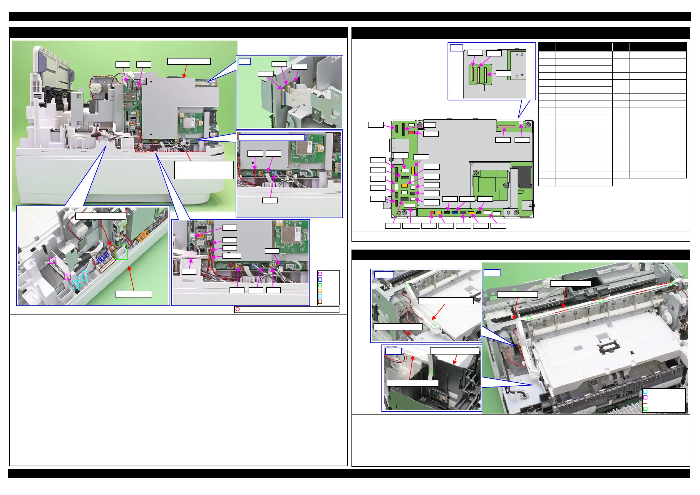
Main Board Unit (1)
Route the following cables as follows.
(For the correspondence between the cables, FFCs and the connectors on the Main Board, see"Main Board Unit (2) (p49)".
• Power Supply Unit cable (CN501): Connect to their connectors on the Main Board.
PF Motor cable (CN7)
APG Sensor cable(CN59)
Relay Board FFC (CN44)
PIS FFC (CN45)
Head FFC (CN41, 42, 43)
• PE Encoder Sensor FFC (CN51): Pull out from the backside of the Main Board Unit and route according to its folds, then connect to the
connector on the Main Board.
• PE sensor cable(CN52): Set the ferrite core into the space shown above, and route through the groove, rib C, and rib D (x4) on
the Frame Base 1st, then connect to the connector on the Main Board.
• CR Motor cable(CN30):
Route through the rib B (x3) and rib C on the Frame Base 1st, then connect to the connector on the Main
APG Motor cable(CN34)
Board.
• Paper Stopper Sensor cable(CN55): Route through the rib A (x2), rib C, and rib D (x4) on the Frame Base 1st, then connect to the
ASF PE Sensor cable(CN56) connector on the Main Board.
• Grounding Wire A: Route through the rib A (x2), hooks (x3), rib B (x3) on the Frame Base 1st, and secure to the position
shown above with the screw.
For WF-7620/WF-7110 Series, route the FFC and cables from the Frame Base 2nd Assy as follows.
•
Frame Base 2nd Assy Paper Stopper sensor cable(CN57):
Connect to their connectors on the Main Board.
ASF Motor cable (CN35)
ASF Encoder Sensor FFC (CN54)
• Grounding Wire B: Route inside the rib C on the Frame Base 1st, and secure together with the grounding wire A to the
position shown above with the screw.
CN501
CN7
CN45
CN51
CN52
CN30
CN34 CN55CN56
Grounding Wire A/B
Frame Base 1st
CN35
Only WF-7620/WF-7610 Series
CN54
CN57
Wall of Frame Base 1st:
Put the excess portion of
cables inside this wall.
CN59CN44
Main Board Unit
Rib A
Rib B
Rib C
Rib D
Hook
Groove
C.B.S-TITE SCREW 3x6 F/ZN-3C (8±1 kgf·cm)
Main Board Unit (2)
The correspondence between Main Board and cables/FFCs is given above.
CN5
CN44
CN60
CN71
CN59
CN70
CN501 CN34
CN73
CN74
CN51
CN35
CN54
CN31
CN30
CN76
CN32
CN52
CN72
CN33
CN57
CN56 CN55
CN45
CN9
CN21 CN53
CN#
名称
CN#
名称
CN5 FAX FFC*
1
CN56 ASF PE Sensor cable*
2
CN9
Wireless LAN Module cable
CN57
Frame Base 2nd Assy Paper
Stopper sensor cable*
2
CN20 Panel FFC
CN30 CR Motor cable CN59 APG Sensor cable
CN31 PF Motor cable CN60 Duplex Unit Cover Open
Sensor cable
CN32 Scanner Motor cable*
1
CN33 ADF motor cable*
1
CN70 Scanner FFC*
1
CN34 APG motor cable CN71 ADF PE Sensor cable*
1
CN35 ASF motor cable*
2
CN72 ADF document sensor
cable*
1
CN41 Head FFC
CN42 Head FFC CN73 ADF encoder sensor
cable*
1
CN43 Head FFC
CN44 Relay Board FFC CN74
Scanner Open Sensor
cable*
1
CN45 PIS FFC
CN51 PF Encoder Sensor FFC CN76 Paper Support Encoder
Sensor cable*
1
CN52 PE Sensor cable
CN53 Cover Open Sensor cable CN77 ADF plunger cable*
1
CN54
ASF Encoder Sensor FFC*
2
CN501
Power Supply Unit cable
CN55
Paper Stopper sensor cable
Note "*1": Only WF-7620/WF-7610 Series
"*2": Only WF-7620/WF-7110 Series
Relay Board FFC
Route the Relay Board FFC as follows.
1. Connect the FFC to the connector (CN2) on the Relay Board Assy and route it through the hook, then secure it to the position shown above with double-
sided tape.
2. Attach the Waste Ink Tray Cover, and pull out the FFC from the inside of the rib on the Waste Ink Tray Cover.
3. Attach the Relay Board FFC Guide, and route the FFC through the ribs (x4) on the guide and secure the FFC to the position on the guide shown above with
double-sided tape (x2).
4. Route the FFC along the standard line on the Main Frame Unit, and secure the FFC to the position on the Main Frame Unit shown above with double-sided tape (x3).
Step2,3
Relay Board FFC Guide
Waste Ink Tray Cover
Step1
Waste Ink Tray Holder
Relay Board FFC Assy
Relay Board FFC
Step4
Hook
Standard line
Rib
Double-sided tape
Main Frame Unit
 Loading...