Epson WF-7620/7610/7110 Series Revision B
Disassembly/Reassembly Routing FFCs/cables 50
Confidential
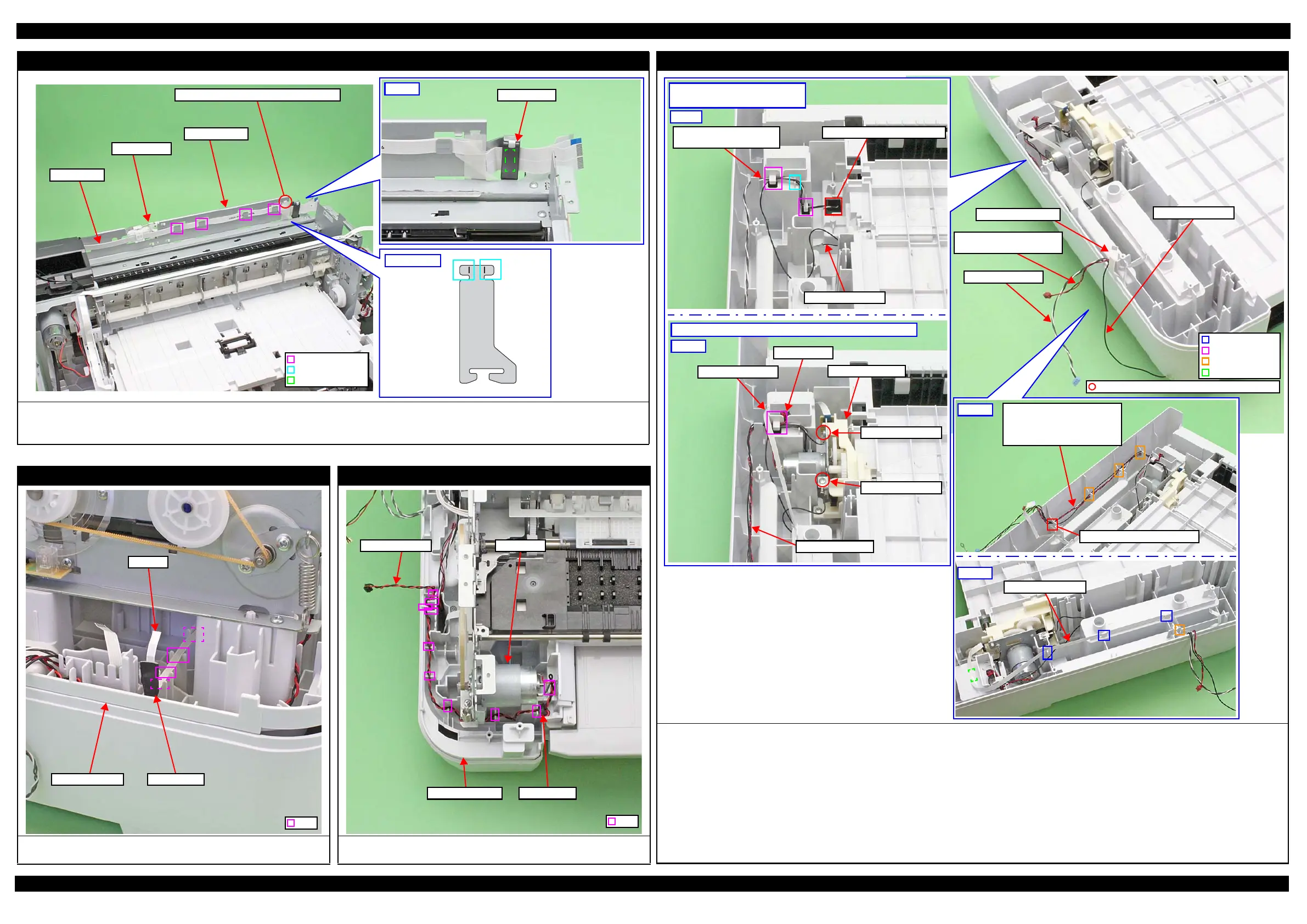
Head FFC
Route the FFC through the hooks (x4) on the Front Frame.
Insert the ferrite core into the position shown above and secure it with double-sided tape.
Attach the FFC Holder and secure the FFC with the holder.
Front Frame
Hook
Double-sided tape
Rib
Fold rib inward into hole on Front Frame.
FFC Holder
Head FFC
PIS FFC
Route the FFC through the ribs (x4) on the Frame Base 1st and secure it to the
position shown above with acetate tape.
PIS FFC
Rib
Acetate TapeFrame Base 1st
PF Motor
Insert the ferrite core into the position shown above, and route the PF Motor
cable through the ribs (x7) on the Frame Base 1st.
PF Motor cable
Ferrite coreFrame Base 1st
PF Motor
Rib
Frame Base 2nd Assy (WF-7620/WF-7110 Series)
Route the cables to the Frame Base 2nd Assy as shown below.
1. Pull out the Frame Base 2nd Assy Paper Stopper sensor cable and grounding wire A from the hole on the Frame Base 2nd Assy, and route the cables
through the ribs and hooks on the Frame Base 2nd Assy. (See Fig. 1.)
2. Install the ASF Motor Assy and wrap the ASF Motor cable around the hook on the Frame Base 2nd Assy once, then insert the ferrite core into the position
shown above. (See Fig. 2.)
3. Secure the grounding wire A to the ASF Motor Assy with the screw, and route the grounding wire B through the ribs and hooks on the Frame Base 2nd
Assy. (See Fig. 2.)
4. Secure the ASF Encoder FFC to the position shown above with double-sided tape. (See Fig. 2.)
5. Route the Frame Base 2nd Assy Paper Stopper sensor cable, ASF Motor cable and grounding wire B through the grooves (x3) and hole on the Frame Base
2nd Assy. (See Fig. 3.)
6. Route the ASF Encoder FFC through the ribs (x3) and the groove on the Frame Base 2nd Assy, and secure it to the position shown above with double-sided
tape. (See Fig. 4.)
Frame Base 2nd Assy
Paper Stopper sensor cable
Grounding Wire A
Top of Frame Base 2nd Assy:
Before ASF Motor Assy is installed
Fig. 1
Hole of Frame Base 2nd Assy
Frame Base 2nd Assy
Paper Stopper sensor cable
ASF Encoder FFC
Fig. 3
• Frame Base 2nd Assy Paper
Stopper sensor cable
•ASF Motor cable
•Grounding Wire B
Hole of Frame Base 2nd Assy
Top of Frame Base 2nd Assy: After ASF Motor Assy is installed
Fig. 2
ASF Encoder FFC
Ferrite core
ASF Motor Assy
ASF Motor Cable
Grounding Wire B
Grounding Wire A
ASF Motor cable
Grounding Wire B
C.B.S-TITE SCREW 3x6 F/ZN-3C (6±1 kgf·cm)
 Loading...