GB-2
GB
Checking the usage
TR 75
Heater with indirect combustion for agricultural sta-
bles and horticultural greenhouses. Depending on
the type and setting, the heater can be operated with
natural gas or LPG (propane/butane).
This function is only guaranteed when used within the
specified limits– see page27 (Technical data). Any
other use is considered as non-compliant.
Type code
Code Description
TR Heater
75 Capacity 75kW, jet length > 50 m
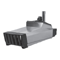
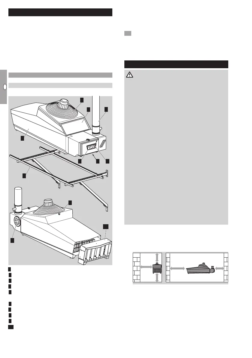
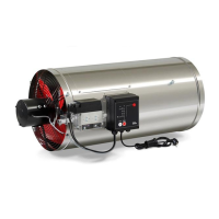
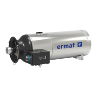
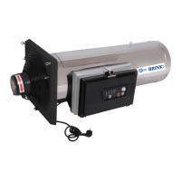
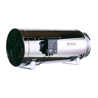
Part designations
M
O
D
E
R
E
SET
O
N
/
O
F
F
2 8
3
6
4
1
9
5
7
10
8
Thermorizer stainless steel housing
Housing cover/Burner control unit
Service flap
4 Connection for gas combination control
5 Chimney with condensate vessel (not included
in the delivery)
6 Main fan
7 Filter
8 Status indicator (operation/faults)
9 Wall bracket (optional)
0 Air diffuser (optional)
Type label
Air circulation, electrical connection rating, rated heat
input, gas type, category, supply pressure, burner
pressure, enclosure: see type label.
• Before installation, check whether the device is
suitable for the regional gas type and the speci-
fied limits, see type code and page27 (Techni-
cal data).
Installation
DANGER
Danger of death! Gases are generated during the
storage of slurry which remain partly dissolved in
the liquid. If the slurry is strongly agitated during
mixing and purging, poisonous, explosive gases
such as hydrogen sulphide and methane are re-
leased. If an ignition source is present, the released
gas can explode.
To avoid damage during operation, please observe
the following:
– Switch off the heater before mixing and purging
the slurry.
– Close the slide valves when storing slurry out-
side.
– The fan for the air supply must not be part of a
closed pipe system.
– Respect the safety distance of the heater to
inflammable materials, see “Installation position”.
– Consult your fire insurance provider and/or local
fire protection engineer to assess the foresee-
able, general risk of fire.
– For cleaning, care and maintenance, note the
applicable national regulations and directives.
– No condensation permitted. Comply with am-
bient temperature, see page27 (Technical
data).
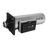
Installation position
▷ Installation position: horizontal.
▷
Note the safety distance to walls and inflam-
mable materials.
> 0,2 m
> 0,5 m
> 0,5 m
> 1 m> 3 m
▷ Ensure sufficient free space around the device.
There must be no obstructions in front of the inlet
and outlet side of the heater.
▷
The distance between the heaters should be
greater than 30m.
▷ To avoid overheating, do not cover the main fan.