GB-9
GB
▷
The main fan cools the heater down until it
reaches switch-off temperature.
CAUTION
– Do not disconnect the heater from the electrical
power supply until the cooling process has been
completed.
▷ The display “–” will go out.
Setting mode
▷
You can go to Setting mode by pressing and
holding the MODE selection button when the
heater is switched off.
• Switch off the heater
OFF 1
2
3
4
5
AUTO
+AUT
MODE
(RESET)
ON/OFF
O
.
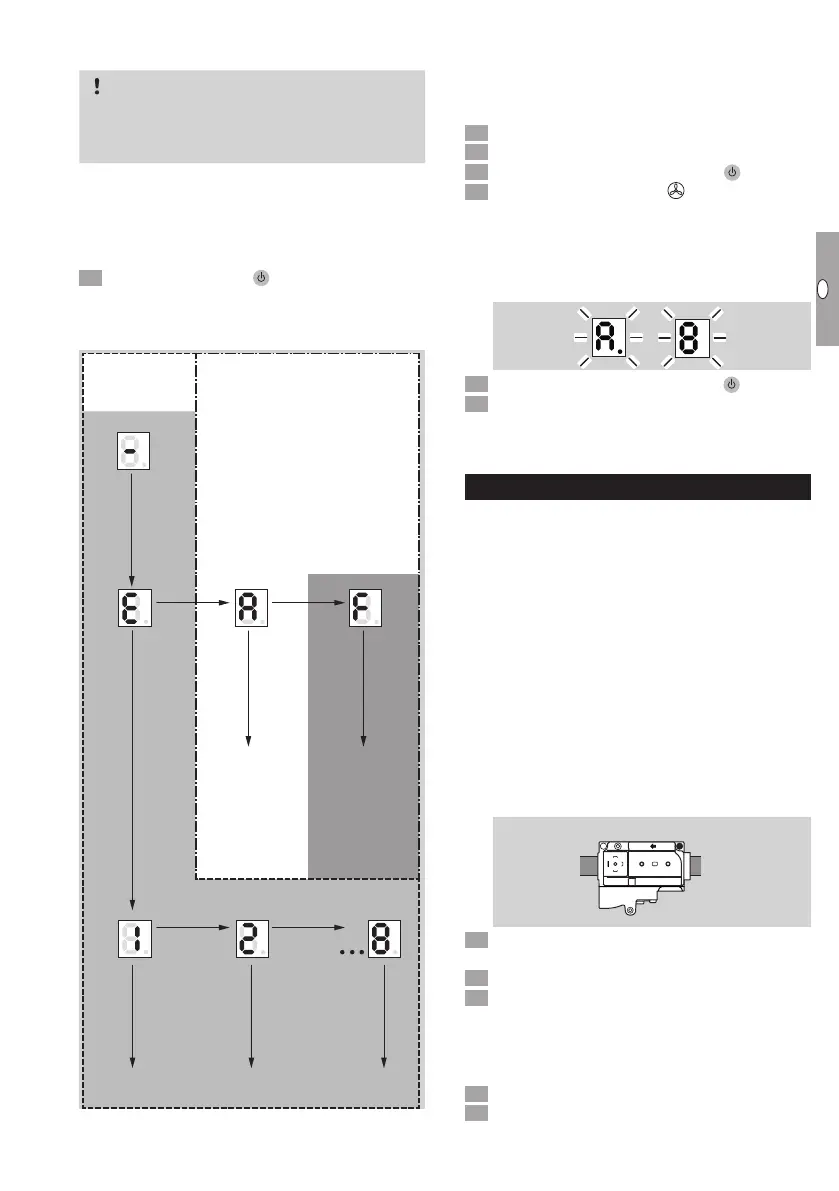
▷
Mode E: eBus addresses can be saved.
Mode A/F: multi-functional outputs can be pa-
rameterized.
MFA 2 MFA 1
eBus address
Mode E
Mode A/F
MODE
button
MODE button
MODE
button
MODE
button
eBus adddress 1 ... eBus address 8
Save eBus address
0 Inactive
1 Fault (NC)
2 Fault (NO)
3 Operation
4 Standby
0 Inactive
1 Main fan
active
2 Main fan
inactive
3 Modulation
enable
> 2 s MODE button
> 2 s MODE button
> 2 s MODE button
> 2 s MODE button
> 2 s MODE button
> 2 s MODE button
> 2 s MODE button
OFF
▷
Press the RESET button to return to the previ-
ous menu.
▷
After a timeout of 20s, the display will auto-
matically return to the initial mode. The display
indicates “–”.
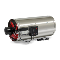
Checking the direction of rotation of the main
fan
Switch on the power supply.
Release the gas supply.
Switch on the TR. Press ON/OFF
OFF 1
2
3
4
5
AUTO
+AUT
MODE
(RESET)
ON/OFF
O
.
4 Select operating mode
3
Controlled air flow.
▷ The main fan will start.
▷
If it is turning in the correct direction, the fan
blades will turn clockwise.
▷
If the direction of rotation is incorrect, fault
codeA 8 will be displayed.
5 Switch off the TR. Press ON/OFF
OFF 1
2
3
4
5
AUTO
+AUT
MODE
(RESET)
ON/OFF
O
.
6 Disconnect the heater from the electrical power
supply and rectify the fault, see page12 (As-
sistance in the event of malfunction).
Adjusting the heater
▷ The heater is set to the gas type specified in the
purchase order.
▷
The fine adjustment on the gas combination
control is made on the basis of the CO
2
meas-
urements on the chimney.
▷ The following are required for setting:
– 2.5mm Allen key,
– pressure gauge with display range 0to 50mbar,
– CO
2
flue gas analyzer. The flue gas analyzer must
be able to measure O
2
, CO and CO
2
. The sen-
sor should be suitable for temperatures of up to
300°C.
▷
The inlet pressurep
u
must comply with the tech-
nical data, see page27 (Technical data).
▷ The inlet pressure p
u
can be measured using a
test point on the combination control.
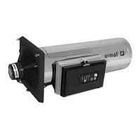
k
p
u
Open test point p
u
.
▷ Do not use force!
Connect a pressure gauge to p
u
.
Disconnect the system from the electrical power
supply.
▷ The heater may only be disconnected from the
electrical power supply once the device has been
switched off and post-cooling is complete.
4 Shut off the gas supply.
5 Remove the plastic cap from the CO
2
test point
on the chimney.