GB-5
GB
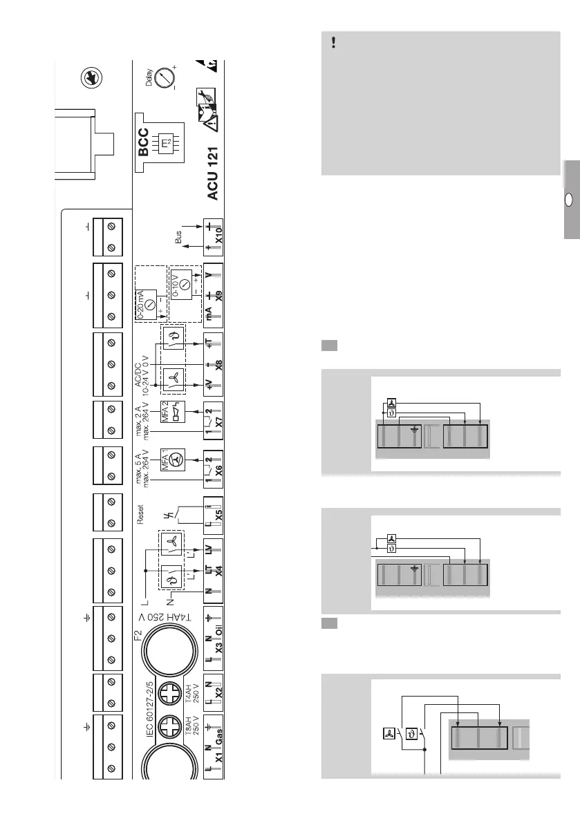
Connection diagram
▷
The burner control unit is fitted with coded plugs
to prevent them being mixed up.
LN LN L
LT LV
+T
–+V
mA
V12
LLiN
12 +
0 V
D – 49018 Osnabrück, Germany
ACU
Connecting the room thermostat
CAUTION
To avoid damage to the heater TR, please observe
the following:
– Provide post-cooling for the TR. The TR requires
a continuous supply of 400VAC (3NAC), 50Hz.
– In case of a power failure, an emergency power
supply unit should automatically take over the
power supply. Emergency power supply units
with a cardan shaft drive for tractor attachment
are also suitable.
▷
Use a room thermostat with a hysteresis of ±1°C.
It switches on if the room temperature is 1°C
less than the set temperature and switches off
again once the room temperature is 1°C more
than the set temperature.
▷
The floating plugs X4 (230V) or X8 (24V) are
used to connect the room thermostat.
▷
If the room thermostat is connected to the
mains supply of other plugs (plug X1 orX3) the
heaterTR will be damaged.
Connecting a single heater to a room
thermostat
6 Connect a room thermostat for 230VAC.
▷ Method 1: power supply via the heater.
230 V AC
+V
– +T
X8
mV
10-24 V AC/DC
X2
230 V AC
L
N
L N
X1 Gas
N
LT LV
X4
X2
L N
X1 Gas
N
LT LV
X4
X2
L N
X1 Gas
N
LT LV
X4
▷ Method 2: power supply via the environmental
control computer.
230 V AC
230 V AC
+V
– +T
X8
mV
10-24 V AC/DC
X2
230 V AC
L
N
L N
X1 Gas
N
LT LV
X4
X2
L N
X1 Gas
N
LT LV
X4
X2
L N
X1 Gas
N
LT LV
X4
6 Connect a room thermostat for 24VDC/AC to
plugX8.
▷ The 24V power supply must always be from an
external source.
+V
– +T
X8
mV
10-24 V AC/DC
X2
230 V AC
L
N
L N
X1 Gas
N
LT LV
X4
X2
L N
X1 Gas
N
LT LV
X4
X2
L N
X1 Gas
N
LT LV
X4
eBus
Burner chip
card (BCC)
Potentiom-
eter
(switch-on
delay)
MFA 2
MFA 1
Remote
reset
0 – 10 V
0 – 20 mA
10 – 24 V
Thermostat
Controlled
air flow
230 V
Thermostat
Controlled
air flow
Mains con-
nection
Mains filter
Mains filter
Mains con-
nection