GB-6
GB
Connecting multiple heaters to a room
thermostat or an environmental control
computer
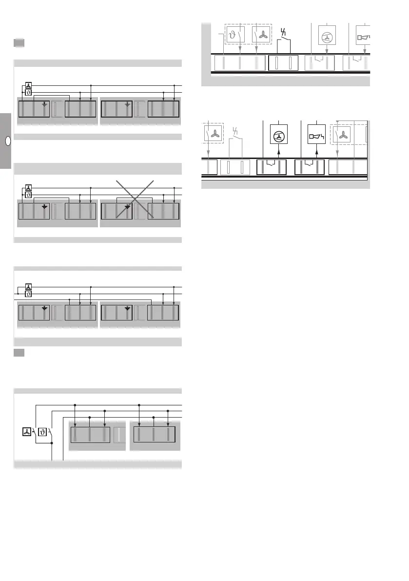
6 Connect a room thermostat for 230VAC.
▷ Method 1: power supply via the heater.
2. TR 75
X2
2. TR 75
– +T
X8
+V
L N
X1 Gas
N
LT LV
X4
2. TR 75
X2
L N
X1 Gas
N
LT LV
X4
2. TR 75
X2
L N
X1 Gas
N
LT LV
X4
1. TR 75
230 V AC
+V
– +T
X8
mV
10-24 V AC/DC
X2
230 V AC
L
N
L N
X1 Gas
N
LT LV
X4
X2
L N
X1 Gas
N
LT LV
X4
X2
L N
X1 Gas
N
LT LV
X4
▷
“N” may only be connected to plug X4 of one
of the heaters.
2. TR 75
X2
2. TR 75
– +T
X8
+V
L N
X1 Gas
N
LT LV
X4
2. TR 75
X2
L N
X1 Gas
N
LT LV
X4
2. TR 75
X2
L N
X1 Gas
N
LT LV
X4
1. TR 75
1. TR 75
1. TR 75
230 V AC
230 V AC
+V
– +T
X8
mV
10-24 V AC/DC
X2
230 V AC
L
N
L N
X1 Gas
N
LT LV
X4
X2
L N
X1 Gas
N
LT LV
X4
▷ Method 2: power supply via the environmental
control computer.
2. TR 75
X2
L N
X1 Gas
N
LT LV
X4
2. TR 75
X2
L N
X1 Gas
N
LT LV
X4
2. TR 75
X2
L N
X1 Gas
N
LT LV
X4
1. TR 75
1. TR 75
1. TR 75
1. TR 75
230 V AC
230 V AC
+V
– +T
X8
mV
10-24 V AC/DC
X2
230 V AC
L
N
L N
X1 Gas
N
LT LV
X4
X2
L N
X1 Gas
N
LT LV
X4
X2
L N
X1 Gas
N
LT LV
X4
6 Connect a room thermostat for 24VDC/AC to
plugX8.
▷
The 24 V power supply must be from an external
source.
2. TR 75
– +T
X8
+V
L N
X1 Gas
N
LT LV
X4
2. TR 75
X2
L N
X1 Gas
N
LT LV
X4
2. TR 75
X2
L N
X1 Gas
N
LT LV
X4
1. TR 75
1. TR 75
1. TR 75
1. TR 75
230 V AC
230 V AC
+V
– +T
X8
mV
10-24 V AC/DC
X2
230 V AC
L
N
L N
X1 Gas
N
LT LV
X4
X2
L N
X1 Gas
N
LT LV
X4
X2
L N
X1 Gas
N
LT LV
X4
Remote reset
N
MFA
FA
2
max. 5 A
max. 264 V
max. 2 A
max. 264 V
N
LT LV
X4
12
X6X5
Li
X7
▷ An external remote reset may be connected to
plugX5.
Multi-functional outputs
MFA 1MFA 2
max. 5 A
max. 264 V
max. 2 A
max. 264 V
AC/DC
10-24 V
LV
+V
–
X8
12
X6X5
Li
12
X7
▷ Floating multi-functional outputs can be param-
eterized using plugs X6 andX7. There are two
methods of completing this parameterization:
The PC software for burner control units
BCSoft can be used via the optical interface on
the burner control unit, see page20 (Acces-
sories).
The “Setting mode” menu can be opened us-
ing the MODE selection button (heater OFF)
and used for parameterizing the outputs, see
page9 (Setting mode).
▷ MFA , external fan (max. 5 A)
For improved air circulation in the room, an addi-
tional fan can be connected. The external fan can
be actuated with an adjustable delay (BCSoft) for
switching it on and off. The exact time relates to
the operation of the main fan.
▷ Possible parameterization options:
– Inactive: the external fan is not actuated.
– Main fan active: the external fan is actuated at
the same time as the main fan.
– Main fan inactive: the external fan is actuated
when the main fan of the TR switches off.
– Modulation enable: the external fan is not actu-
ated until the TR starts modulating operation.
▷ MFA , status signal (max. 2A)
Possible parameterization options:
– Fault NO (default setting):
For example, the input for a horn can be set to
NO.
– Fault NC:
The input on an environmental control computer
can be set to NC (e.g. to indicate a cable dis-
continuity).
– Operation
– Standby