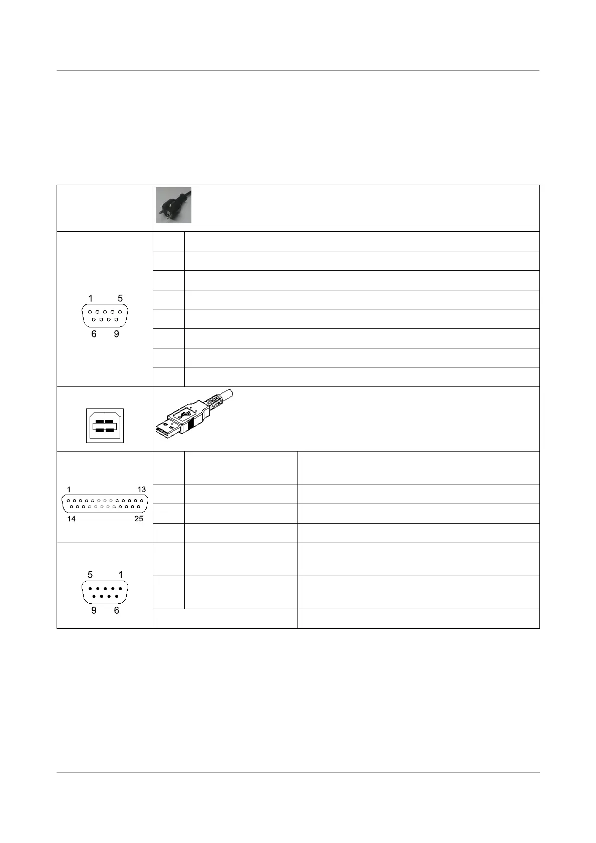
3 Connection Diagram
Power
85 – 264 VAC, 0.45 A, 50/60 Hz
Note: Always use Earthed/Grounded Mains socket.
Load Cell
Pin Value
1 - Signal
2 + Signal
3 - Sense (Note: If load cell is 4-wire connect -Excitation here)
4 + Sense (Note: If load cell is 4-wire connect +Excitation here)
5 Ground - Shield
6 + Excitation
7 - Excitation
USB
RS-232
Pin Signal
PC Connection
(Type-D 9-Pin Male)
2 Tx 2 (Rx)
3 Rx 3 (Tx)
7 Gnd 5 (Gnd)
Remote Display
Pin Signal
ERTE HG57 Remote Display Connection
(Type-D 9-Pin Female)
1, 2,
3
NC No connection
4, 5, 6, 7, 8, 9 4, 5, 6, 7, 8, 9 one-to-one
v1.00 Page 7