ESAB CUTMASTER 100
OPERATION 300X5397
4T-6
7. Clean spatter and scale from the shield cup and
the tip as soon as possible. Spraying the shield
cup in anti - spatter compound will minimize the
amount of scale which adheres to it.
Cutting speed depends on material, thickness, and the
operator’s ability to accurately follow the desired cut line.
The following factors may have an impact on system
performance:
• Torch parts wear
• Air quality
• Line voltage uctuations
• Torch standoff height
• Proper work cable connection
4T.05 Gouging
WARNING
Be sure the operator is equipped
with proper gloves, clothing, eye and
ear protection and that all safety pre-
cautions at the front of this manual
have been followed. Make sure no
part of the operator’s body comes in
contact with the workpiece when the
torch is activated.
Disconnect primary power to the
system before disassembling the
torch, leads, or power supply.
!
CAUTION
Sparks from plasma gouging can
cause damage to coated, painted or
other surfaces such as glass, plas-
tic, and metal.
Check torch parts. The torch parts
must correspond with the type of
operation. Refer to Section 4T.07,
Torch Parts Selection.
Gouging Parameters
Gouging performance depends on parameters such
as torch travel speed, current level, lead angle (the
angle between the torch and workpiece), and the dis-
tance between the torch tip and workpiece (standoff).
!
CAUTION
Touching the torch tip or shield cup
to the work surface will cause exces-
sive parts wear.
Torch Travel Speed
NOTE!
Refer to Appendix Pages for addi-
tional information as related to the
Power Supply used.
Optimum torch travel speed is dependent on current
setting, lead angle, and mode of operation (hand or
machine torch).
Current Setting
Current settings depend on torch travel speed,
mode of operation (hand or machine torch), and the
amount of material to be removed.
Pressure Setting
Even though the setting is within the specied range,
if the torch does not pilot well the pressure may need
to be reduced.
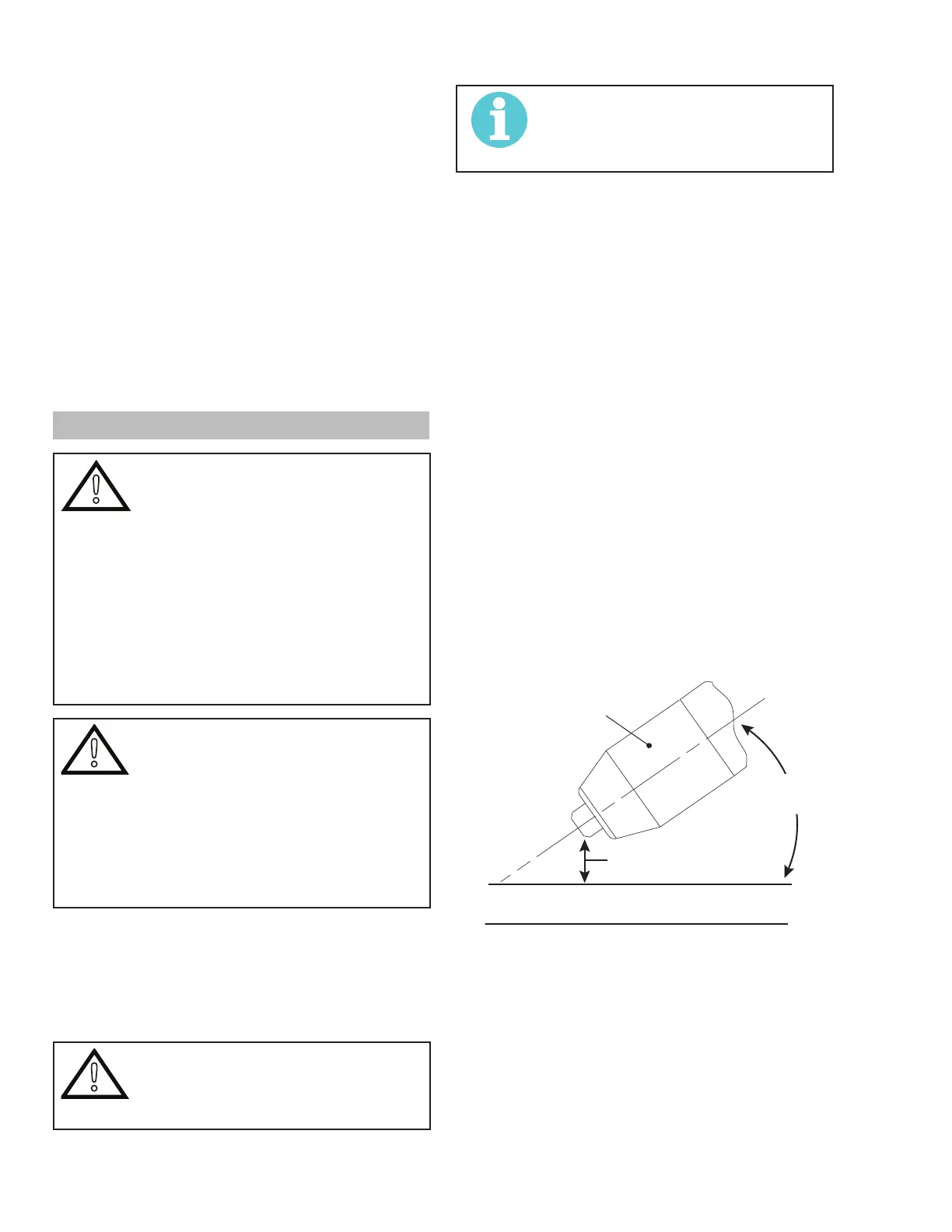
Lead Angle
The angle between the torch and workpiece depends
on the output current setting and torch travel speed.
The recommended lead angle is 35°. At a lead angle
greater than 45° the molten metal will not be blown
out of the gouge and may be blown back onto the
torch. If the lead angle is too small (less than 35°),
less material may be removed, requiring more pass-
es. In some applications, such as removing welds
or working with light metal, this may be desirable.
35°
Workpiece
Torch Head
Standoff Height
A-00941_AB
Gouging Angle and Standoff Distance
Standoff Distance
The tip to work distance affects gouge quality and
depth. Standoff distance of 1/8 - 1/4 inch (3 - 6
mm) allows for smooth, consistent metal removal.
Smaller standoff distances may result in a severance
cut rather than a gouge. Standoff distances greater
than 1/4 inch (6 mm) may result in minimal metal
removal or loss of transferred main arc.