ESAB CUTMASTER 100
INSTALLATION 300X5397
3-2
!
CAUTION
The primary power source and pow-
er cable must conform to local elec-
trical code and the recommended
circuit protection and wiring require-
ments (refer to table in Section 2).
6. Connect the wires as follows.
• Wires to L1, L2 and L3 input. It does not
matter what order these wires are attached.
See previous illustration and on label in the
power supply.
• Green / Yellow wire to Ground.
7. With a little slack in the wires, tighten the through
- hole protector to secure the power cable.
8. Reinstall the Power Supply cover per instructions
found in section 5.
9. Connect the opposite end of individual wires to
a customer supplied plug or main disconnect.
10. Connect the input power cable (or close the main
disconnect switch) to supply power.
3.04 Gas Connections
Connecting Gas Supply to Unit
The connection is the same for compressed air or high
pressure cylinders. Refer to the following two subsec-
tions if an optional air line lter is to be installed.
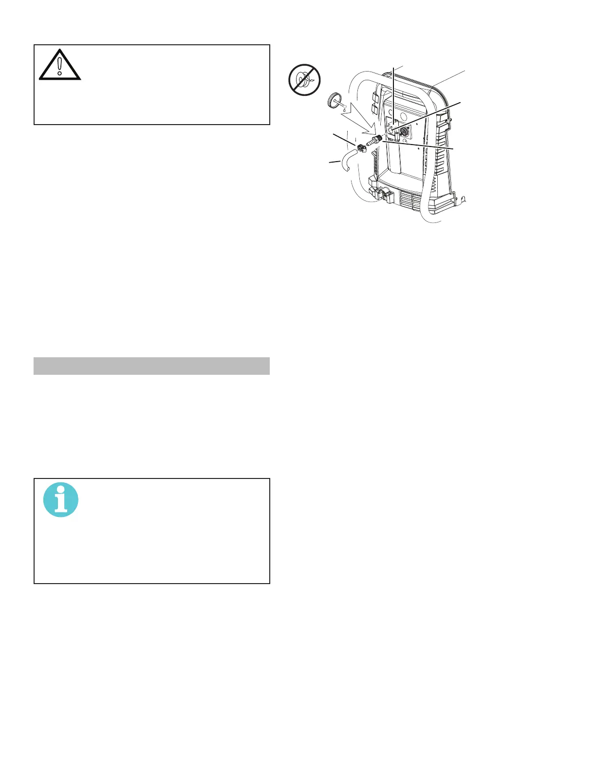
1. Connect the air line to the inlet port. The illustra-
tion shows typical ttings as an example.
NOTE!
For a secure seal, apply thread
sealant to the tting threads, accord-
ing to manufacturer's instructions.
Do not use Teon tape as a thread
sealer, as small particles of the tape
may break off and block the small air
passages in the torch.
Art # A-07943
Hose Clamp
Assembly
Inlet Port
1/4 NPT or ISO-R
Air Connection to Inlet Port
Installing Optional Single - Stage Air Filter
An optional lter kit is recommended for improved lter-
ing with compressed air, to keep moisture and debris
out of the torch.
1. Attach the Single - Stage Filter Hose to the Inlet
Port.
2. Attach the Filter Assembly to the lter hose.
3. Connect the air line to the Filter. The illustration
shows typical ttings as an example.