ESAB CUTMASTER 100
SERVICE 300X5397
5-6
5.06 Power Supply Basic Parts
Replacement
!
WARNING
Disconnect primary power to the
system before disassembling the
torch, leads, or power supply.
This section describes procedures for basic parts
replacement. For more detailed parts replacement
procedures, refer to the Power Supply Service Manual.
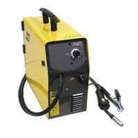
A. Cover Removal
1. Remove the NOTE screws which secure the
cover to the main assembly. Do not loosen the
lower screws inside the cut out slots in the bottom
of the cover.
Art # A-08429
Lower
Screws
Lower
Slots
Upper
Screws
2. Carefully pull the Cover up and away from the
unit.
B. Cover Installation
1. Reconnect the ground wire, if necessary.
2. Place the cover onto the power supply so that
slots in the bottom edges of the cover engage
the lower screws.
3. Tighten lower screws.
4. Reinstall and tighten the upper screws.
C. Filter Element Assembly Replacement
The Filter Element Assembly is in the rear panel. For
better system performance, the lter element should be
checked per the Maintenance Schedule (Subsection
5.02), and either cleaned or replaced.
1. Remove power from the power supply; turn OFF
the gas supply and bleed down the system.
2. Remove the system cover. See "A Cover Re-
moval" in this section.
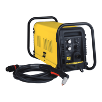
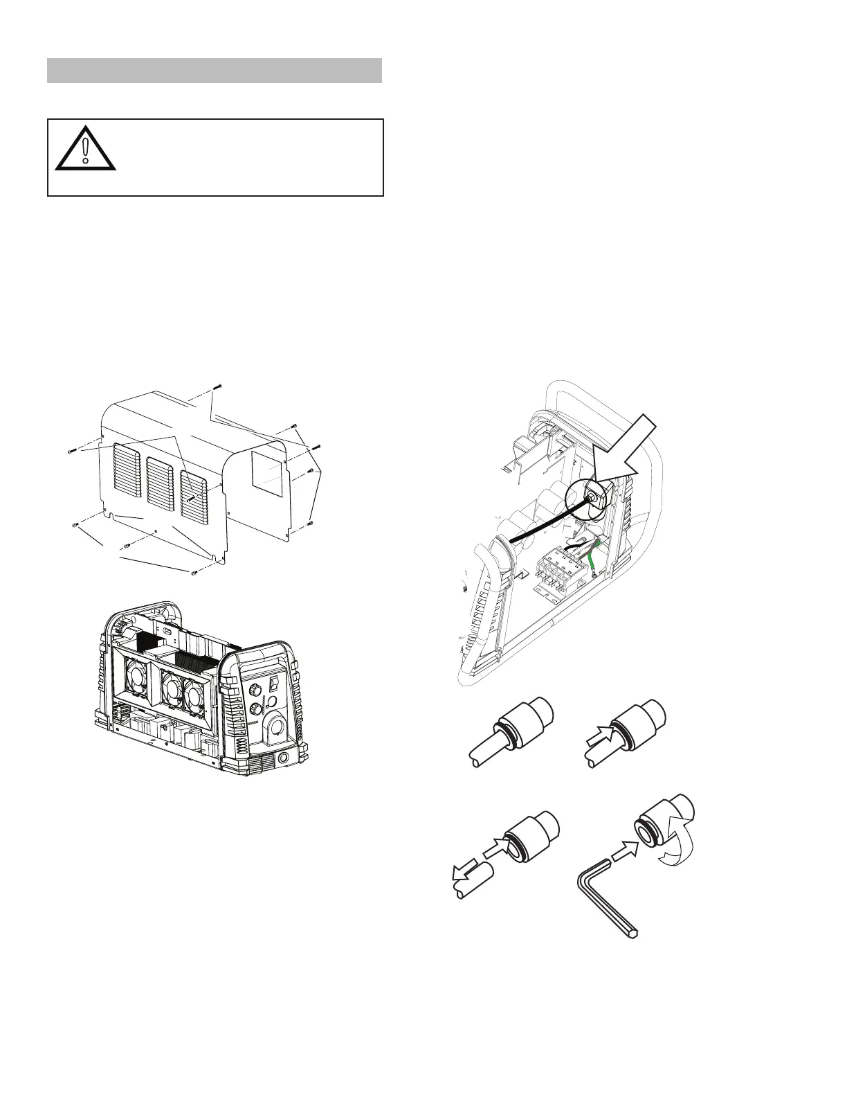
3. Locate the internal air line and the tting from
the lter assembly. Number 1 in the following
illustration.
4. Hold a wrench or similar tool against the locking
ring on the lter assembly tting, then pull on
the hose to release it. (Numbers 2 and 3 in the
following illustration).
Art # A-07989
1
2
3
4
5
6mm