– 64 –
405,505e
6 OPERATION
General safety regulations for the handling of the equipment can be found on
page 56. Read through before you start using the equipment!
WARNING – TIPPING RISK!
There is a risk of tipping while transportation and operation, if the welding machine leans
more than 10
o
. In that case appropriate securing has to be provided !
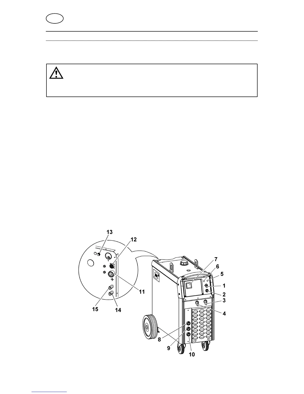
6.1 Connection and control devices
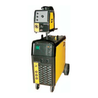
1 Mains supply switch 9 Connection for return cable (–), medium in-
ductance
2 Main supply switch for cooling unit ELP** 10 Connection for return cable (–), low induc-
tance
3 Switch, precise control 11 Connection for welding current cable (+)
4 Switch, coarse control 12 Connection for control cable for wire feeder
5 Indicating lamp, power supply ON 13 MCB
6 Orange indicating lamp, overheating and
loss of coolant*
14 Connection RED for cooling water from the
wire feed unit
7 Space for digital meter (optional), see page
203
15 Connection BLUE for cooling water to the
wire feed unit
8 Connection for return cable (–), high induc-
tance
NOTE! Cooling water connections only available on certain models.
* Indicating loss of coolant, only when water flow guard is used, see point 6.2.4
** ELP = ESAB Logic Pump, see point 6.2.3.
GB


 To Next Page