EasyManua.ls Logo

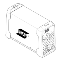
ESAB ES 150i User Manual

ESAB ES 150i
64 pages
To Next Page IconTo Next Page
Page #1 background imageLoading...
Page #1 background image
Service manual
0463 714 001 GB 20201008
Valid for: Serial No. HA017-, HA018-, HA019-, HA020-, HA026-,
HA027-xxxx-xxxx
ES150i, ES180i,
ES180iPro,ES200iPro,
ET180i, ET 200iP, ET 200iP Pro
Question and Answer IconNeed help?

Do you have a question about the ESAB ES 150i and is the answer not in the manual?

ESAB ES 150i Specifications

General IconGeneral
Input Voltage230 V
Input Current16 A
Output Current Range10-150 A
TechnologyInverter
Open Circuit Voltage63 V
Electrode SizeUp to 3.2 mm
Protection ClassIP23S

Summary

Read This First Safety Guidelines

Product and Serial Number Compatibility

Lists products and their valid serial numbers for manual applicability.

Safety and Function Responsibility

Clarifies integrator's responsibility for safe setup and product function.

Mandatory Instruction Manual Review

Emphasizes the importance of reading the instruction manual before installation or operation.

Static Electricity Precautions

Service Preparation and Tools

Recommended Service Aids and Tools

Lists antistatic kits, test boxes, and measuring devices for service.

Introduction to Welding Power Sources

Power Source Design and Modules

Explains the inverter principle and the main function modules of the power source.

ES 150i/ES 180i Component Identification

Pro Model Component Identification

Machine Labels and Panel Identification

Rating Plate Specifications and Warranty

MMA and TIG Torch Installation Guide

Power Source Schematic Diagrams

ES 150i/180i Schematic Block Diagram

Presents a block diagram illustrating the functional flow of the ES 150i/180i power source.

Pro Model Schematic Block Diagram

Presents a block diagram illustrating the functional flow of the Pro models.

Power Source Functional Block Explanations

Error Codes and Service Log Descriptions

Error Code E01: Thermal Protection Troubleshooting

Details error code E01, its meaning, and recommended troubleshooting actions.

Wiring Diagrams and Component Descriptions

Input Rectifier and Filter Circuit Functions

Explains the purpose of the input rectifier and filter components in AC to DC conversion.

Secondary Rectifier (FRD) Functionality

Wiring Diagram: ES 150i and ES 180i

Wiring Diagram: ES 180i Pro and ES 200i Pro

Wiring Diagram: ES 180i Pro/200i Pro Alternate View

Wiring Diagram: ET 180i

Wiring Diagram: ET 200iP

Wiring Diagram: ET 200iP Pro

ES 150i/180i Internal Component Layout

Main PCB, Transformer, and IGBT Identification

Inverter PCB Board Component Details

IGBT and Rectifier PCB Component Testing

ES 180i Pro/200i Pro Internal Component Layout

Pro Models: Main PCB, Transformer, IGBT Identification

PFC Board Component Identification

Pro Models: Inverter PCB Board Component Details

Pro Models: IGBT and Rectifier PCB Component Testing

ET Models: Internal Component Layout Overview

Technical Data: ES 150i and ES 180i

ES 150i/180i Electrical and Performance Specifications

Provides detailed technical data including voltage, current, duty cycle, and efficiency.

ES 180i Pro/200i Pro Electrical and Performance Specifications

ES 180i Pro/200i Pro Environmental and Physical Specifications

Technical Data: ET 180i

ET 180i Electrical and Performance Specifications

Provides technical data for the ET 180i, including voltage, current, and efficiency.

ET 180i Environmental and Physical Specifications

Technical Data: ET 200iP

ET 200iP Electrical and Performance Specifications

Provides technical data for the ET 200iP, including voltage, current, and efficiency.

ET 200iP Pro Electrical and Performance Specifications

ET 200iP Pro Environmental and Supply Specifications

Panel Operation and Settings

Adjusting High Current Output Regulation

Explains the procedure for adjusting the power source's high current output.

Accessing and Using Hidden Functions

Details how to activate and use hidden settings for TIG and MMA processes.

VRD Function: Activation and Deactivation

Troubleshooting: Initial Checks and Component Testing

Pre-Power Up Checks and Visual Inspection

Guides on safety checks before power-on and visual examination for damage.

Primary Diode Bridge Voltage Testing

Instructs on testing the primary diode bridge using a multimeter's diode setting.

IGBT and Secondary Diode (FRD) Testing

Overload Protection Indicator (E01)

Explains the E01 error code related to overload protection and cooling.

Troubleshooting No Power and Start-Up Issues

Power Up Check Procedures

Details the steps to follow after completing pre-power up checks.

PCB Voltage and Open Circuit Voltage Tests

Power ON Indicator and Fan Operation Tests

Front Panel Display and Control Troubleshooting

Troubleshooting No Output and Welding Functionality

Fan Malfunction and Low Output Voltage Diagnostics

Advanced IGBT Drive and Transformer Waveform Analysis

Remote Signal Troubleshooting with Mains Voltage

Current Sensor Signal Troubleshooting

In-Service Inspection and Testing Procedures

General Requirements and Test Conditions

Outlines personnel qualifications, test environment, and instrument accuracy standards.

Periodic Inspection and Electrical Testing

Describes the process for periodic inspections, including visual and electrical tests.

Cleaning Instructions and Safety Precautions

Provides guidelines for cleaning the welding equipment and required safety measures.

Post-Repair Inspection and Testing Protocol

Comprehensive Visual Inspection Checklist

Electrical Safety and Performance Testing

Functional Test Procedures for Welding Operation

In-Service Test Report Documentation

Spare Parts and Manual Information

Accessing Spare Parts and Documentation

Information on obtaining spare parts lists and relevant instruction manuals.

Related product manuals