TROUBLESHOOTING
0463 714 001
- 44 -
© ESAB AB 2020
TROUBLESHOOTING
Fault tracing
Pre power up checks
WARNING!
Make sure the power source is disconnected from the mains supply and wait at
least 5 minutes for the DC bus capacitor to discharge before removing any of the
power source panels!
Then remove the power source left side panel and measure the voltage between the
"+" and "-" soldering surface of the capacitor, using a multimeter. If the voltage
between the "+" and "-" soldering surface of the capacitor is not < 20 V, wait further
until the voltage is below 20 V!
Visual Inspection
Examine the power source for any visible signs of damage. Especially check:
1. Printed circuit boards for burned varistors or other components
2. Cables and connectors
Components testing
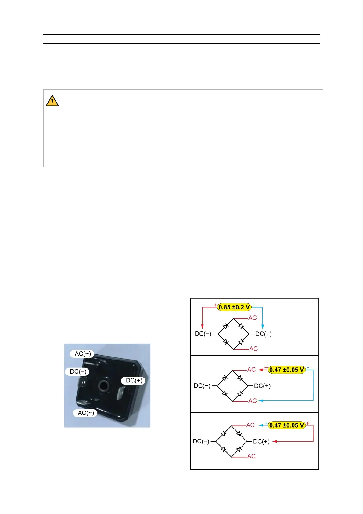
Primary diode bridge
Use a multimeter set to diode test setting.
Connect the negative probe to DC+ and positive probe to DC-, it should read 0.85±0.2V.
Negative and positive probe each connected to AC-, it should read 0.47V±0.05V.
Connect positive probe to DC -, and negative probe to AC-, it should read 0.47V±0.05V.