14
SECTION 3 INSTALLATION
ELECTRIC SHOCK CAN KILL!
PROVIDE MAXIMUM PROTECTION AGAINST ELECTRICAL SHOCK. BE
FORE ANY CONNECTIONS ARE MADE INSIDE THE MACHINE, OPEN
THE LINE WALL DISCONNECT SWITCH TO TURN POWER OFF.
WARNING
3.4 Input Connections to Console
3.4.1 Primary Power Specications
ESP-200 is a 3-phase unit. Input power must be provided from a line (wall) disconnect switch that contains fuses or circuit
breakers in accordance to local or state regulations.
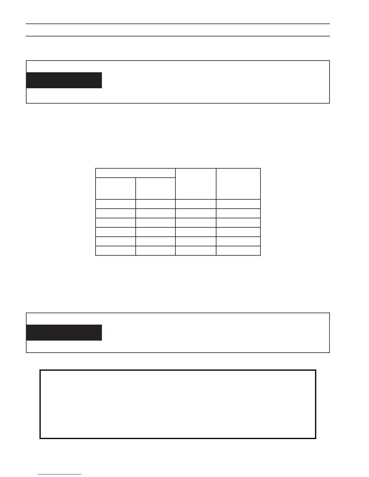
Recommended input conductor and line fuse sizes:
Rated Load Input and
Ground
conductor*
CU/AWG
Time delay
Fuse size
(amperes)
Volts Amperes
200/208 140 2/0 200
230 121 1/0 150
380 74 No.2 100
415 66 No.4 100
460 62 No.4 100
575 48 No.6 70
*Sizes per National Electrical Code for a 75 °C rated copper conductors @ 40 °C ambient. Not more than four conductors
in raceway or cable. Local codes should be followed if they specify sizes other than those listed above. Input current
values given in this table are at maximum output power (40kW) 200 amps at 200VDC.
Dedicated power line may be necessary.
ESP-200 is equipped with line voltage compensation but to avoid
impaired performance due to an overloaded circuit, a dedicated
power line may be required.
NOTICE
NOTE !!!
380/415V CE Mains Supply Requirements:
High power equipment may, due to the primary current drawn from the mains supply, inuence the pow-
er quality of the grid. Therefore connection restrictions or requirements regarding the maximum permis-
sible mains impedance or the required minimum supply capacity at the interface point to the public grid
may apply for some types of equipment (see technical data). In this case it is the responsibility of the
installer or user of the equipment to ensure, by consultation with the distribution network operator if
necessary, that the equipment may be connected.