22
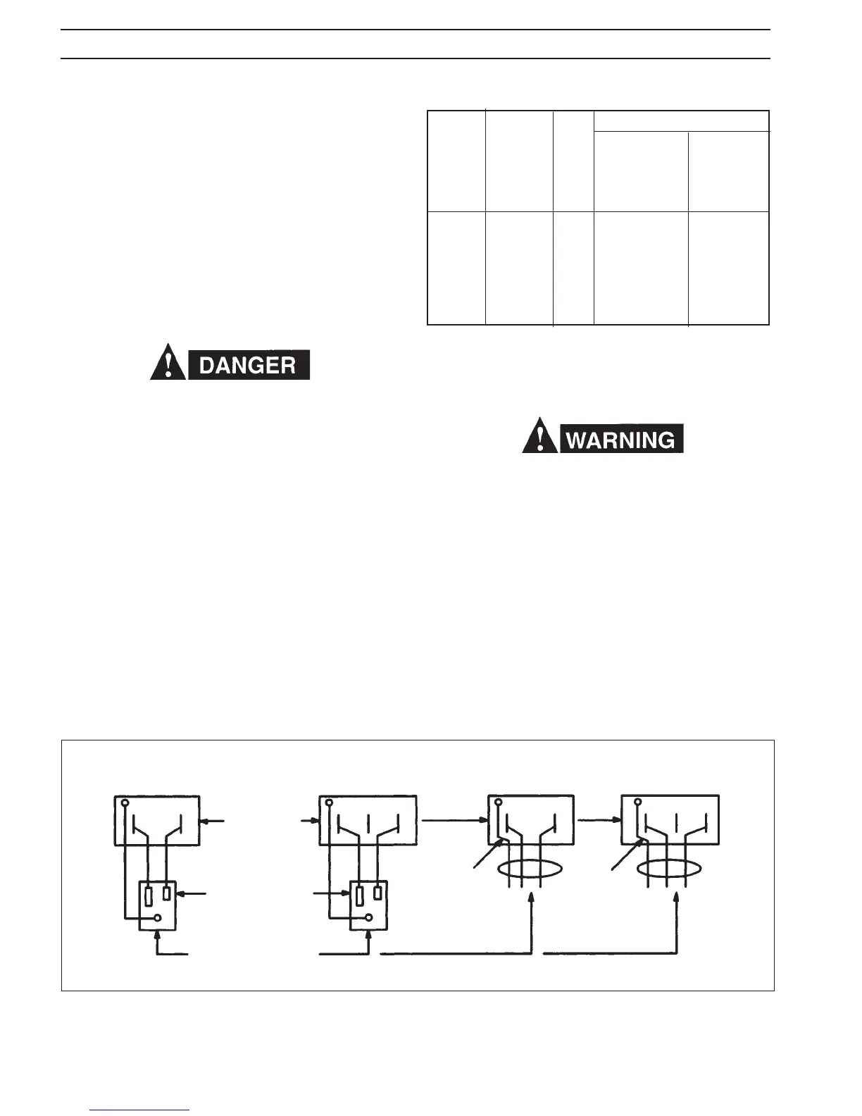
Figure 3.2 - Primary Connection
208/230 MODEL ONLY (With Plug-Cap)
208/230/380/400/460/575-V. MODELS
SINGLE-PHASE
THREE-PHASE
SINGLE-PHASE
THREE-PHASE
GRD
GRD
GREEN
CONDUCTOR
(GROUND)
GREEN
Fused
Line
Disconnect
Switch,
or
Circuit Breaker
Wall Receptacle
MIGMASTER SYSTEM
CONNECTS HERE
Figure 3.2 A
Figure 3.2 B
Figure 3.2 D Figure 3.2 C
TABLE 3.1 Input Conductor and Fuse Size
Recommended
Full Primary
Primary Load Input Ground
Input Line Fuse Conductor Conductor
Volts Amperes Size Size Size
208 71 90 8 8
230 62 90 8 8
380 37 50 10 10
400 36 50 10 10
460 31 40 12 12
575 25 30 12 12
Figure 3.3A - Primary Reconnections at Switch For
208/230 Volt Models
The terminal labeled GRD is connected to the welding
machine chassis and is for ground purposes only. It must
be connected to a good electrical ground. Do not connect
a conductor from the terminal labeled GRD to any one of
the L1, L2 terminals as this will result in an electrically hot
welding machine chassis.
Figure 3.2A illustrates wiring to a single phase system and
Figure 3.2B illustrates wiring to a three phase system.
The 208/230/380/400/460/575 primary input voltage unit is
provided with a three conductor primary input cable without
plugcap. The ground lead of this cable should be connected
to a reliable ground and the two remaining wires should be
connected to the separately fused lines of the disconnect
or breaker as shown in Figures 3.2C and 3.2D.
All machines leave the factory with their primary electrical
input requirements internally-connected for the highest
voltage rating available in each model (e.g.: 230-volt for
the 208/230-volt units; and 575-volt for the "multi-voltage"
units).
Only qualied personnel should make these changes. Make
certain the primary power has been disconnected and all
safety procedures have been followed before proceeding
with these instructions.
Fig. 3.3A shows the 230v and 208v connections for the
208/230 dual voltage model. Change over is made by remov-
ing the right side panel below the wire feed compartment
and switching the primary transformer tap at the top of the
power switch with the unused alternate voltage tap located
next to the main transformer (see Fig. 3.3B). Both voltage taps
(the one currently connected to the switch and the unused
alternate voltage) are marked with the input voltage require-
ment. All units are supplied from the factory connected for
the highest voltage (230 vac). Before switching the voltage
taps, verify the actual voltage requirement as well as the
current voltage connection to be certain re-connection
is necessary. If voltage tap re-connection is necessary, the
following paragraphs cover the procedure to switch the
voltage tap for either 208vac or 230vac input.
GRD
GRD
SECTION 3 INSTALLATION