30
The FINE VOLTAGE ADJUSTMENT Selector is an eight-
position switch by which the operator selects the exact
amount of arc voltage (or heat) to be applied to the weld
(within the coarse range selected above). This allows you
to ne-tune the voltage required; the higher the number
selected (1-8), the hotter the weld. The Fine Voltage Selector
switch also has an "open" detent at the six o'clock position.
Placing the switch in this position allows operation of the
torch trigger to feed electrode wire without the wire being
electrically "hot". This switch also, must not be switched
under load.
These tap switches carry several hundred am-
peres, and must not be switched under load, as
this will cause the contacts of the switches to arc.
4.1.3 SECONDARY WELDING CONNECTIONS
The secondary contactor, with parallel poles, is used to make
and break the circuit between the transformer secondary
and the rectier. This contactor is turned on and o when
the torch trigger (in the 24 volt circuit) is operated.
The secondary output welding terminals, POS.(+) and
NEG(-), are located in the right side wire feeding compart-
ment and are used to set the welding polarity (D.C.R.P. or
D.C.S.P.) in which the machine will operate (see Fig. 4.1).
As shipped from the factory, the 250 is set up to operate
in D.C.R.P. (TORCH tting is connected to Positive, and
WORK cable/clamp is connected to Negative output). To
weld using D.C.S.P., simply mount the WORK cable to the
Positive output and the TORCH tting cable to the Nega-
tive output terminal.
4.1.4 CONTACTOR CONTROL
Refer to the schematic diagrams. Note that the coil of the
24 volt contactor is activated with the torch trigger and is
energized when the trigger is pulled. The gas solenoid is
in parallel with the contactor coil and is energized at the
same time.
When the trigger switch is released, the contactor drops
out and disconnects the load.
Because of the charged capacitor bank in the second-
ary circuit, the output voltage will take a few seconds
before falling to zero volts.
The gas valve shuts o when the contactor opens.
4.1.5 WIRE FEED SPEED CONTROL
Wire feed speed is controlled by the wire speed potentiom-
eter knob on the front panel. The solid state control allows
for innitely variable speeds up to 650 IPM.
This wire speed pot is used to set the speed at which the
welding wire is fed out from the torch and hence the weld-
ing amperage. The panel-face numbers on the dial (0-10)
are used for reference and do not directly indicate wire feed
speed; the higher the number, the faster the speed.
4.1.6 STD./SPOOL GUN SELECTOR
This two-position toggle switch is located inside the unit
on the mid-wall of the wire feeding compartment and is
labeled Standard and Spool Gun. It is used to select standard
metal inert gas welding (MIG) with the GUNMASTER 250, or
welding with the ST-23A (spool-on-gun) torch.
4.2 PROCESS SETUP
4.2.1 STANDARD MIG SEAM WELDING W/
GUNMASTER 250
Refer to Sections 4.3.1, 4.3.2, 4.3.3, 4.3.4, and Table 4.3.3.
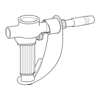
4.2.2 ST-23A SPOOL-ON-GUN CONTROL
CONNECTION/OPERATION
The Migmaster 250 is equipped with a built-in control for
the Spool Gun which operates via the amphenol control
receptacle and a screw adaptor that provides Gas and Power.
The ST-23A Torch (see Section 2.4.3) has a amphenol-plug
control cable connection, and a gas/power cable, see Figure
4.2.2.
To operate the unit with the ST-23A Torch connected, do
the following (refer to Fig. 4.2.2):
A. Place the STD./Spool Gun selector toggle switch (4.1.6)
in the 250 to its Spool Gun position.
B. Connect the ST-23A control cable amphenol to the re-
ceptacle labeled CONTROL on the 250’s front panel.
C. Remove the threaded plastic plug from the Gas/Power
adaptor (on the 250's front panel) using a clockwise
rotation. Connect the ST-23A gas/power cable to the
panel adaptor using a counter-clockwise rotation. As
shipped from the factory, the 250's secondary output
power terminals are set-up for D.C.R.P. welding polar-
ity (see Section 4.1.3).
SECTION 4 OPERATION