24
3.4 TORCH CONNECTIONS
The torch (GUNMASTER 250), which is supplied as standard
equipment with the Migmaster 250 System, is provided
with a euro-type adapter which directly connects to the
torch tting mounted on the front panel. Line up matching
holes, push on and tighten locking collar. As shipped from
the factory, the euro or common connector type torches
are set-up for D.C.R.P. welding polarity (see sections 3.3
or 4.1.3). To connect the spool-on-gun torch (ST-23A) see
Section 4.2.2.
3.5 WIRE FEEDER MECHANISM
3.5.1 DRIVE ROLLS
The drive roll has two grooves: the small groove feeds 0.035
in. diameter wire, the large groove feeds 0.045 in. wire. The
groove nearest the gear motor feeds the wire. If the required
groove is not in that position:
A. Release the pressure drive roll lever and lift the
assembly upward.
B. Remove the two (2) screws holding the drive roll to
the gear.
C. Reverse the drive roll on the drive roll shaft.
D. Replace the screws and tighten.
E. Secure the pressure drive roll assembly.
3.5.2 WELDING WIRE SPOOL
As with any work area, make sure safety glasses with side
shields are worn when handling or changing wire or clip-
ping wire o at the spool or at the end of the torch. Hold
onto the wire coming o the spool with one hand before
clipping. Serious eye injury can result due to the springi-
ness of the wire which can quickly unravel, or a cut wire
end which may shoot across the room.
Install a spool of welding wire on the hub as follows:
A. Unscrew spool nut from hub.
B. Place wire spool on hub to rotate clockwise as wire
is unwound; hub pin must engage hole in spool.
C. Replace nut.
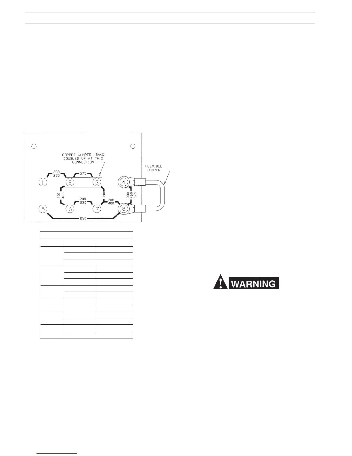
3.2.5 RECONNECTING FROM 575 VAC INPUT
Figure 3.3.1 shows you how to reconnect the "multi-voltage"
model from a 575-volt input to any of the remaining avail-
able voltage inputs 200 or 380 or 400 or 460-volts. These
connections are made by unscrewing the right side panel
below the wire feeding compartment, and locating the
primary voltage changeover terminal board handing in the
center of the lower compartment. This board contains copper
links which must be reconnected to match the silk-screened
voltage designations for the input you plan to use (it comes
factory-connected for a 575-volt input), see Figure 3.3.1.
3.3 SECONDARY OUTPUT CONNECTIONS
The Migmaster 250 Welding System is completely self-
contained so that the front panel torch ttings (Euro-type
MT and Spool gun) are internally connected to the welding
polarity (D.C. Reverse or D.C. Straight) via the secondary
output terminals located inside the wire feeding compart-
ment (see Fig. 4.1). The machine comes set up for D.C.R.P.
welding as described in Section 4.1.3.
Figure 3.3.1-Primary Reconnections at Voltage Changeover Terminal
Board for 208/230/380/400/460/575Volt Models
PRIMARY VOLTAGE CONNECTION CHART
VOLTAGE CONNECTION NO. OF STRIPS
1 - 2 1
208 6 - 7 1
7 - 8 FLEX
1 - 2 1
230 6 - 7 1
5 - 8 FLEX
380 3 - 7 2
4 - 8 FLEX
400 2 - 6 2
7 - 8 FLEX
460 2 - 6 2
4 - 8 FLEX
575 2 - 3 2
4 - 8 FLEX
SECTION 3 INSTALLATION