29
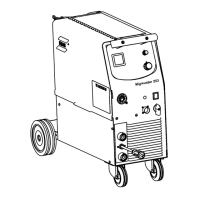
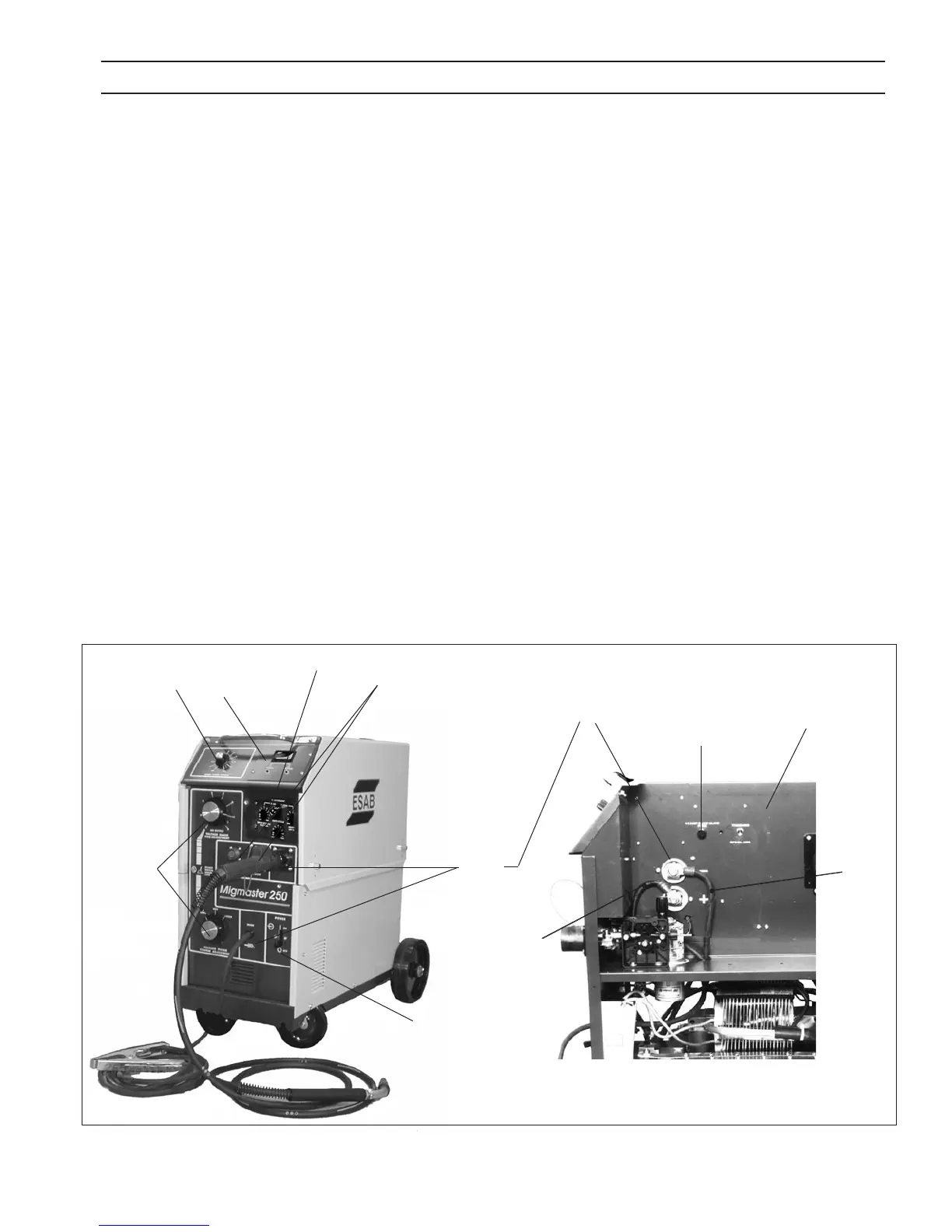
4.1 CONTROLS (See Figure 4.1)
4.1.1 POWER SWITCH
A line toggle switch on the front panel energizes the pri-
mary of the main transformer. This switch also turns on the
fan, which is connected across a portion of the primary
winding.
Two transformer secondary windings also become ener-
gized:
A. Gun trigger circuit 24 volts AC.
Wire feeder circuit 24 volts DC.
B. Main welding secondary circuit. Depending upon
the tap switch position, various secondary volt-
ages can be obtained. Then rectied, open circuit
voltages can be selected between 18 and 56 volts
DC when the secondary contactor is energized.
4.1.2 VOLTAGE CONTROL (Coarse Range Selector
and Fine Adjustment Range Selector)
Voltage control is by means of two high current tap switches
which connect the rectier bridge to various secondary
taps.
The COARSE VOLTAGE RANGE Selector is a three-position
switch, LOW/MED/HIGH, by which the operator selects the
approximate range of voltage (or heat, that determines the
arc length) to be applied to the weld. It is a coarse selection
control and is used in conjunction with the Fine Voltage
Adjustment selector following. It must not be switched
under load.
4.1.5
2.4.2
4.2.3
4.1.3
4.1.1
4.1.2
Torch
Cable
4.1.6
4.2.2
Secondary Output Terminals
for Welding Polarity Change-over,
see 4.1.3.
10A. Fuse
Work
Cable
SECTION 4 OPERATION