25
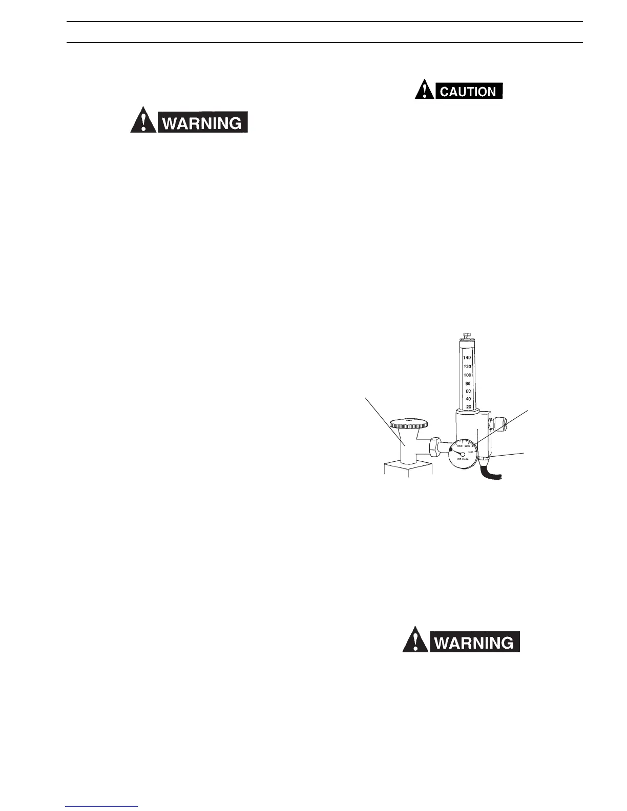
OUTLET
CONNECTION
CYLINDER
PRESSURE
GAUGE
Do Not adapt R-33-FM-580 for use with CO
2
. Relief device
may rupture if CO
2
is used with the R-33-FM-580. For CO
2
service, order R-33-FM-320, P/N 21558.
a. With the cylinder cap in place CAREFULLY slide
the cylinder of gas onto the Migmaster 250 cylinder
rack.
b. Secure the cylinder to the unit, using the chain
provided.
c. Unscrew the cylinder cap.
d. Open the cylinder valve slightly, just for an instant,
to blow away any dirt or dust which may have ac-
cumulated in the cylinder valve outlet. Be sure to
keep your face away from the valve outlet
to protect your eyes.
e. Attach the regulator to the cylinder valve, tighten
the union nut securely with a 1-1/8in. open end or an
adjustable wrench.
Fig. 3.6 R-33-FM-580 Regulator (Illustrated)
CYLINDER
VALVE
3.5.3 THREADING WELDING WIRE
A. Turn o power switch.
When the power switch is on, and gun trigger is depressed,
the electrode wire becomes electrically hot, and the wire
feed rolls are activated.
B. Release pressure drive roll assembly and lift up
ward. Check that proper wire diameter groove is in
the inner position.
CAUTION: Before threading welding wire through casing,
make sure chisel point and burrs have been
removed from wire end to prevent wire from
jamming in gun casing or liner.
C. Feed the wire from the spool through the inlet
guide, across the drive roll groove and into gun
outlet guide.
Make sure that the proper “outlet guide tube” is inserted
into the front-panel gun tting for the size and type of
wire being used, see Table 2.4.5.2 for wire feed accessories
(Section 2.4.5).
To insure proper wire feeding, it is important that the wire
be kept clean and that the drive rolls be periodically cleaned
of any chips or scale that might be carried into the gun liner
and cause sticking.
D. Lower pressure roll assembly and secure. Check
that the gears mesh. Feed wire through to gun tip
with gun trigger (power ON).
3.5.4 BRAKE DRAG ADJUSTMENT
Brake disc friction should provide enough drag to keep the
wire spool or core from spinning freely after wire feed stops.
If adjustment is required, turn adjusting screw clockwise to
increase drag, counterclockwise to decrease it. Drag should
be just low enough to limit wire
overrun.
3.6 CONNECTION OF SHIELDING GAS SUPPLY
The R-33-FM-580 Regulator-Flowmeter is designed for use
with an argon or argon-mix cylinder of shielding gas. It is
adjustable for delivering up to 50 cfh through the torch. To
set up the system do the following:
SECTION 3 INSTALLATION
f. Attach the gas hose from the rear of the Migmaster 250
to the regulator outlet connection (see Fig. 3.6).
g. Slowly open the cylinder valve a fraction of a turn.
When the regulator pressure gauge pointer stops
moving, open the cylinder valve fully.
Never stand directly in front of or behind the regulator when
opening the cylinder valve. Always stand to one side.