26
h. Using a leak test solution, such as P/N 998771 (8 oz. con-
tainer) or soapy water, test for leakage about the cylinder
valve stem, the regulator inlet connection, and the hose
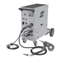
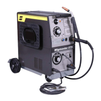
connections at the regulator and at the Migmaster 250
for leakage. Correct any leaks before starting work.
i. If work is to be stopped for a half-hour or more, or the
regulator is to be removed from the cylinder, shut down
the regulator as follows:
a. Close the cylinder valve.
b. Release gas from the regulator by closing the torch
trigger lever.
c. When pressure gauge drops to zero, the regulator is
de-pressurized and shutdown.
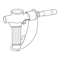
j. Each regulator is equipped with a porous metal inlet
lter, P/N 71Z33, pressed into the regulator inlet nipple.
No. regulator should be connected to a cylinder or station
valve unless it contains this lter. You can replace the lter
if you have reason to do so. To remove a lter refer to the
regulator instruction literature for details.
k. Regulators in need of repair should be returned to your
Welding Equipment distributor or to an authorized Re-
manufacturing Center.
If welding is performed in a conned area, shielding gas leaks
could result in a buildup of shielding gas concentration, displac-
ing oxygen, thereby endangering personnel enter the area.
3.7 WELDING CABLE CONNECTIONS
Connect the work clamp solidly to the workpiece or work table.
Clamp onto a bare metal area.
A good electrical connection to the work is essential to proper
welding operation and to prevent electric shock.
Welding cables should be kept as short as possible and be of
adequate current carrying capacity. Resistance of the welding
cables and connections causes a voltage drop which is added
to the voltage drop of the arc. Excessive cable resistance may
result in a reduction of the maximum usable current output
of the equipment.
SECTION 3 INSTALLATION
The proper operation of this equipment is to a large extent
dependent on the use of welding cables and connections
which are in good condition and of adequate size.
3.8 ASSEMBLE REAR WHEELS
The unit's running board is factory assembled except for the
rear wheels which are packed loose in the shipping carton.
The rear gear consists of 2-wheels, 4-washers, 2-cotter pins,
and an axle. To install the gear, do the following:
a. Insert the axle through the holes provided at the rear
of the gear.
b. Place a washer onto each end of the axle, then slip on
the wheels, then add another washer to the outside
of each wheel, and secure the whole assembly by
inserting a pin in each end of the axle.
c. Remove the existing shipping supports by unscrew-
ing from chassis.
3.9 INSTALLING OPTIONAL SPOT/STITCH/ANTI-
STICK MODULE
a. Remove lower blank-cover plate from upper-right
front panel of power supply -- save the four mount-
ing screws.
b. Locate the harness-connected 15-pin plastic plug,
P3, inside the mounting cavity. Note that this plug
will have a jumper plug with jumper wires con-
nected to it -- remove (and save) the jumper plug.
(The jumper plug must be reinstalled if the module
is ever removed.
c. Connect the 15-pin plug into the matching receptacle
on the rear of the optional control module. The plug
will only t one way.
d. Install the control module in place of the blank panel
removed in Step a., using the same four screws that
you saved.