34
E. Never operate the equipment at currents greater than
the rated ampere capacity; overheating will occur.
F. Never operate equipment in a damp or wet area
without suitable insulation for protection against
shock. Keep hands, feet and clothing dry at all
times.
G. Whenever the equipment is left unattended, turn
all control and power supply switches and gas
supplies OFF and open the main line switch.
H. Wear dark substantial clothing to protect exposed
skin from arcburn, sparks and ying hot metal.
I. Turn o welding power before adjusting or replacing
electrodes.
Never operate the welding machine with any portion of
the outer enclosure removed. In addition to a hazard,
improper cooling may result in damage to the welding
transformer and the welding machine components.
Warranty is void if the machine is operated with any
portion of the outer enclosure removed.
4.3.2 PRE-WELD REQUIREMENTS
Before welding commences, with all power OFF, check
the following:
A. All safety requirements have been read and under-
stood.
B. All hoses and cables are in good condition, safely
insulated and securely connected.
C. Turn on gas supply by slowly opening cylinder
valve to full ON.
D. Correct size wire accessories have been installed
on the wire feeder, drive gears are meshed, wire
pressure set, and guide tube is installed for type
and size wire you plan to use, refer to Tables
2.4.5, and 4.3.
E. Spool of correct size wire is locked in place, brake
tension is set, and wire is properly threaded
through the inlet guide to the gun tip.
F. The wire feeding compartment cover is closed
and secure.
G. Make sure that the metal to be welded is properly
prepared:
a. Remove loose surface rust, scale or paint with
wire brush or sander.
b. Attempting to weld over grease or oil can cause
weld defects.
c. Before welding on aluminum, be sure to clean
surface thoroughly using a stainless steel brush.
4.3.3 SET-UP PROCEDURE
A. Determine the material type, thickness and joint
conguration to be welded from Table 4.3 and use
the recommendations to set the following:
a. Coarse Voltage Range, LOW/MED/HIGH.
b. Fine Arc Voltage Setting, 1 thru 8 (the higher the
number, the hotter the weld).
c. Wire Speed setting, 0 thru 10 (the higher the
number, the faster the speed).
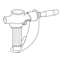
B. Set the two-position switch in the wire feeder com-
partment to STANDARD for seam welding with the
GUNMASTER 250 torch. (For ST-23A Spool-On-Gun
welding, see Section 4.2.2).
C. If optional Spot/Stitch/Anti-Stick Control module is
installed, refer to Section 4.2.3 for operation, settings
and welding condition table.
D. Make sure the GUNMASTER 250 torch tting and
the “Work” cable are connected to the proper output
terminals (inside unit) for the polarity desired.
Only qualied personnel should make these changes.
Make certain the primary power has been disconnected
and all safety procedures have been followed before
proceeding with these instructions.
Normally, you will set-up for “reverse polarity”; this
means the torch tting is connected to the POS (+)
output terminal and the “Work” cable to the NEG (-)
output terminal.
For “straight polarity”, do just the opposite; torch tting
to NEG (-) output terminal and “Work” cable to
POS (+) output terminal.
4.3.4 WELDING OPERATION
A. Turn Power switch (on unit) to ON position -- be
careful not to operate the torch switch.
B. Before starting the weld, the welding wire should
extend about 1/2-inch beyond the end of the nozzle.
Adjust this length by either clipping o the end of the
wire with insulated cutters or by using the torch
switch.
SECTION 4 OPERATION