35
Power supply contactor becomes energized the moment
the torch trigger is depressed. Arcing can occur if the
wire is brought to a ground. Keep the torch away from
ground until welding is to begin.
C. To start the weld, hold the torch so the welding wire is
approximately 1/4-in. from the work, then press the
torch trigger.
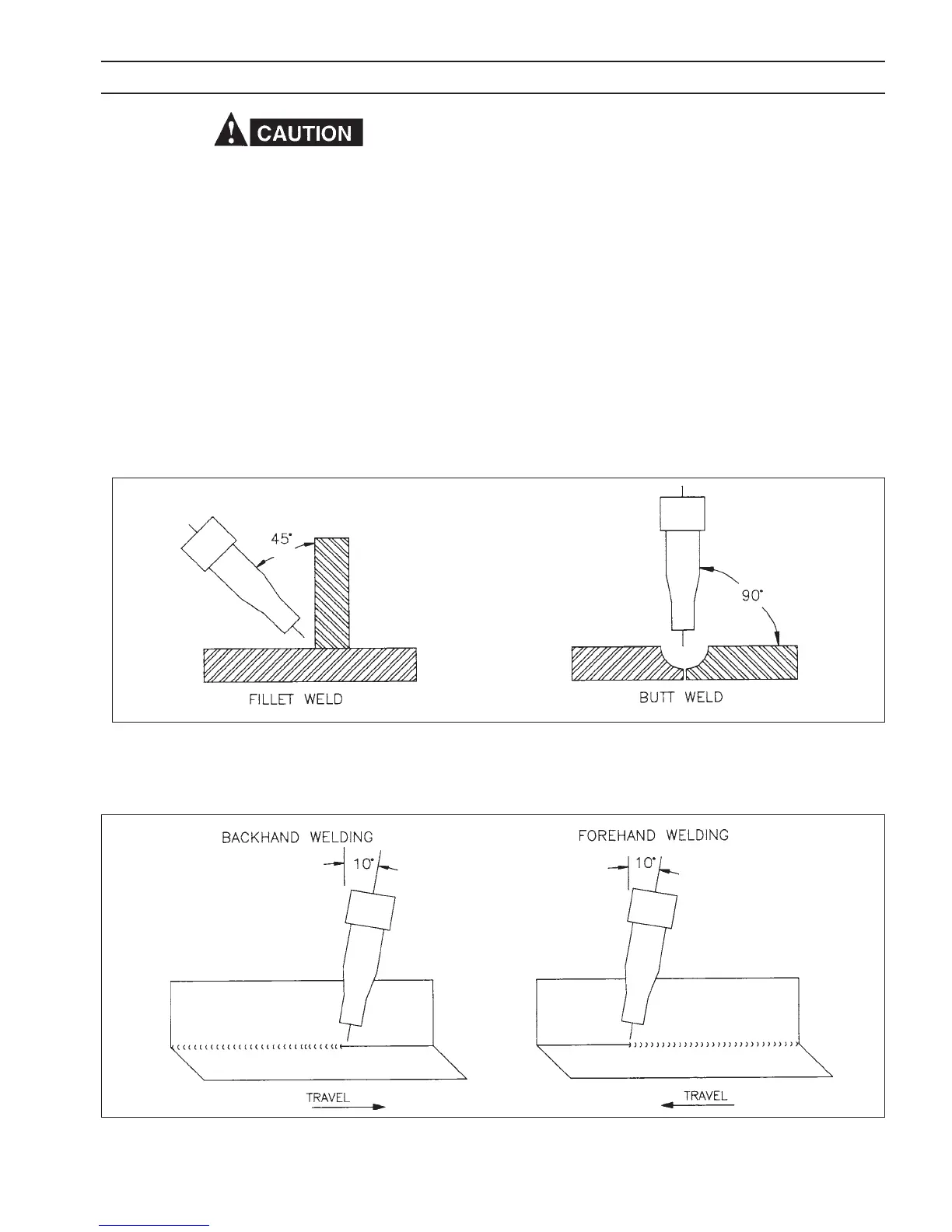
D. The welding wire should be pointed into the joint
at angles of approximately 45
0
for llet welds, and
approximately 90
0
for butt welds, (Fig 4.3.4.1).
E. The torch angle relative to the length of the weld should
be approximately 10
0
from the vertical (Fig. 4.3.4.2).
F. When welding in the vertical position, traveling either
up or down, it is very important to keep the arc on the
leading edge of the puddle to ensure complete penetra-
tion.
G. Some welders who are accustomed to welding with stick
electrodes may tend to push the torch into the weld.
This is neither necessary nor desirable, since the wire
electrode is being mechanically fed into the weld.
Please note that the Wire Speed control can be adjusted
for the gauge of metal to be welded. However, the
Coarse Voltage Range and Fine Voltage setting must
not be switched while welding.
H. To stop the weld, release the trigger and pull the torch
from the work. When leaving equipment unattended,
always shut OFF and disconnect all input power and
shut o shielding gas at source.
TABLE 4.3, Continuous/Stitch Weld Conditions
Fig. 4.3.4.1 - Angle of Welding Wire with Joint
SECTION 4 OPERATION