EasyManua.ls Logo

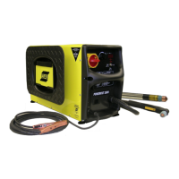
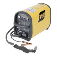
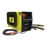
ESAB PowerCut 1600 Service Manual

ESAB PowerCut 1600
184 pages
To Next Page IconTo Next Page
Page #1 background imageLoading...
Page #1 background image
Service Manual
Manual # 0558008016- Rev. 0 11/2008
This manual provides service / troubleshooting
instructions for PC1600 consoles beginning with
Serial Number .........PORJ815099
ending with Serial Number ....PORJ852108
Powercut 1600
Plasmarc Cutting Package
PART NO DESCRIPTION
0558007230 PC1600 230/460V Console
0558007230F PC1600 230/460V BL Console
0558007237 PC1600 575V BL Console
0558007636 PC1600 400V Console
0558007234 PC1600 400V CE Console
0558008323 PC1600 460V Console
(BL = Bilingual)

Table of Contents

Other manuals for ESAB PowerCut 1600

Question and Answer IconNeed help?

Do you have a question about the ESAB PowerCut 1600 and is the answer not in the manual?

ESAB PowerCut 1600 Specifications

General IconGeneral
BrandESAB
ModelPowerCut 1600
CategoryWelding System
LanguageEnglish

Summary

SECTION 1 SAFETY PRECAUTIONS

Personal Safety Precautions

Protects against arc rays, noise, and burns from welding processes.

Fire and Explosion Prevention

Guidance on preventing fires and explosions during operation.

Electrical Shock Hazards

Precautions to avoid severe injury or death from electricity.

Fumes and Gases Safety

Safety measures for ventilation and avoiding toxic fumes.

Compressed Gas Cylinder Handling

Safe practices for handling compressed gas cylinders.

SECTION 3 SPECIFICATIONS

SECTION 4 DESCRIPTION OF OPERATION

Machine Testing and Troubleshooting

Procedures for testing, troubleshooting, and servicing the unit.

Main Power Switch S1 Operation

Description and testing of the main power switch.

Control Transformer T2 Function

Function and schematic of the control transformer.

Input Bridge Rectifier Details

Details of the 3-phase full-wave rectifier.

Contactor K1 Relay Function

Description of the main power relay.

Voltage Selector Switch SW2 Operation

Function of the switch for input voltage selection.

Main Transformer T1 Operation

Operation and schematic of the main transformer.

Output Diodes D101, D102 Description

Description of the output diode modules.

PCB1 Control/Display Board Overview

Overview of the main control and display board.

Input Inductor L1 Specifications

Function and specifications of the input inductor.

Power PC Board Overview

Description of the power board and its components.

Power Driver Boards PCB3/PCB4

Details on the IGBT driver boards.

SECTION 5 WIRING DIAGRAMS

SECTION 6 REPLACEMENT PARTS

SECTION 8 ERRORS

Troubleshooting Error 13

Troubleshooting steps for Error 13 (PIP test failure).

Troubleshooting Error 15

Troubleshooting steps for Error 15 (voltage buildup failure).
SECTION 9 GENERAL INFORMATION

Related product manuals