630298_3 EF5000 Installation Guide - US
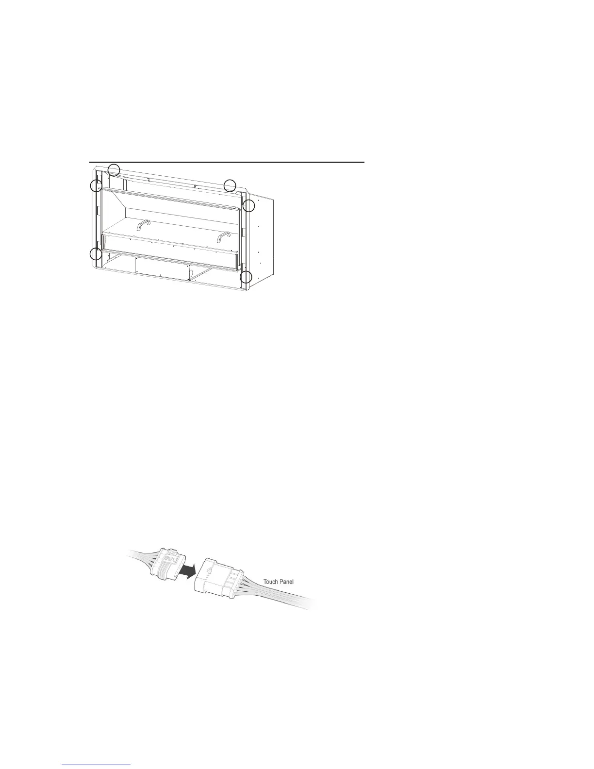
9.0 Fixing the fire into the cavity:
To fix the fire to the cavity, first drill 4 to 6 (3/16” diameter) holes in the outer flange (as
shaded grey in the picture below) in locations which will give you the most support from the
cavity framework behind, and evenly spaced around the flange. Using the supplied Stainless
Steel screws, fasten the fire to the cavity through these drilled holes.
Ensure that the fire is securely located and free from movement.
Suggested location of screws for mounting
10.0 Connecting the Gas Pipe:
When the fire unit has been pushed into position and secured the gas pipe can be
connected to the Dormont hose (1/2” NPT) at the front left of the fire. The hose and pipe
assembly should have been tested prior to this as per section 8.2.
10.1 The EF5000 must be isolated from the gas supply piping system during any pressure testing
of that system at test pressures in excess of ½ psi (14”WC).
The gas fireplace and its individual shutoff valve must be disconnected from the gas supply
piping during any pressure testing of that system at test pressures in excess of ½ psi (3.5
kPa – 14” w.c.).
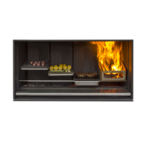
11.0 Connecting the Touch panel:
11.1 The Touch Panel is located on the RH side of the Fascia.
11.2 The Touch Panel socket plugs into the 5 pin plug lead situated at the front RH side of the
fire. Push them together until they ‘click’,
12.0 Testing of the Touch panel and spark ignition:
IMPORTANT: Before the operating pressure can be checked and the fascia fitted,
The touch panel and spark ignition must be tested.
12.1 This can be done with the gas supply either turned on or off.
With the power supply and touch panel connected, Lean the fascia ‘Right end’ up beside the
fire and run through the steps for igniting the pilot (refer to section 17.0 for instructions).