Starting Up
3. Starting Up
To start up the CAN-PN follow the instructions below.
Step Procedure
see
page
Read the safety instructions at the beginning of this document
carefully, before you start with the hardware installation!
5
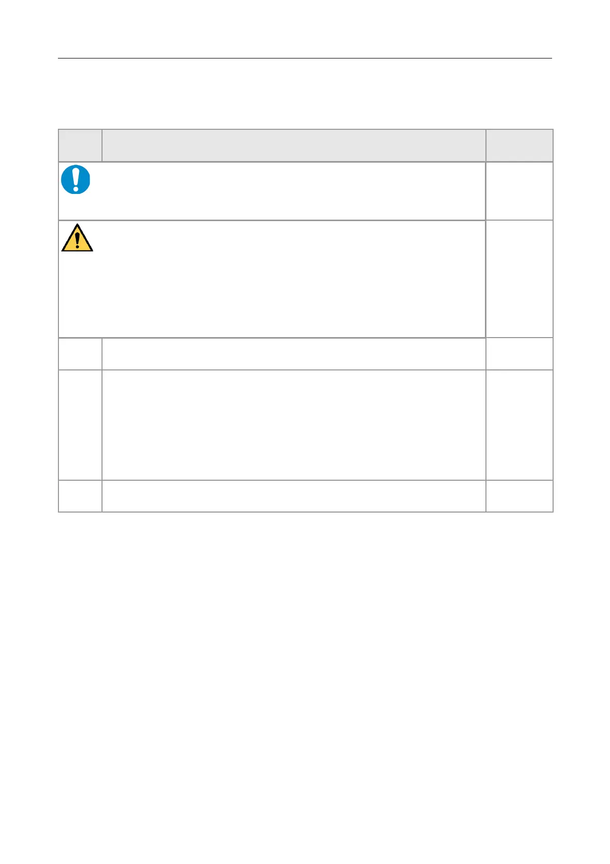
Danger
Hazardous Voltage - Risk of electric shock due to unintentional contact with
uninsulated live parts with high voltages inside of the system into which the
CAN-PN is to be integrated.
→
→
All current circuits which are connected to the device have to be
sufficiently protected against hazardous voltage (SELV according to
EN 60950-1) before you start with the installation.
Ensure the absence of voltage before starting any electrical work.
1. Mount the CAN-PN module and connect power supply voltage CAN bus
and PROFINET-IO.
10
2. Please note that the CAN bus has to be terminated at both ends!
esd offers special T-connectors and termination connectors for external
termination.
Additionally the CAN_GND signal has to be connected to earth at exactly
one point in the CAN network. All esd termination devices will provide a
corresponding contact.
For details please read chapter “Correct Wiring of Electrically Isolated CAN
Networks”.
21
3. Continue with the installation of the software, as described in the software
manual of the CAN-PN in chapter: 'Implementation'.
-
CAN-PN
Hardware Manual • Doc. No.: C.2920.21 / Rev. 1.4
Page 13 of 38