Do you have a question about the ESD CAN-DP/2 and is the answer not in the manual?
Information on qualified personnel, product conformity, EU directives, and warnings.
Details on product application, service notes, and proper disposal methods.
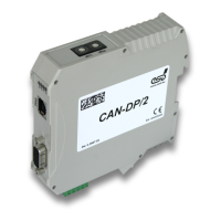
Describes the CAN-DP/2 and CANopen-DP/2 modules, their architecture, and interfaces.
Details the assignment and display functions of the LEDs on the front panel.
Explains how to set the PROFIBUS-DP address using coding switches.
Provides general specifications like power supply, connectors, temperature, and dimensions.
Details the CPU, SRAM, Flash-EPROM, and Serial EEPROM specifications.
Specifies the number of interfaces, controller, physical layer, and isolation.
Outlines the DP controller, interface, and connector for PROFIBUS-DP.
Describes the diagnostic service interface, type, specification, and connector.
Details the pin assignment and signal description for the CAN bus connector.
Explains the pin assignment and signal description for the PROFIBUS-DP interface.
Describes the pin assignment and signal description for the power supply connector.
Provides details on conductor connection methods and cross-section specifications.
General rules for wiring CAN networks in light industrial environments using single twisted pair cables.
General rules for wiring CAN networks in heavy industrial environments using double twisted pair cables.
Guidelines for electrical grounding and recommended bus lengths for CAN networks.
Provides examples of suitable CAN cables for light and heavy industrial applications.
Explains how to test and resolve termination problems in CAN networks.
Covers electrical grounding checks and short circuit detection in CAN wiring.
Describes how to test CAN transceiver voltages and internal resistance for faults.
Details the connector assignment for 24V and CAN signals via InRailBus.
Guides on installing modules and connecting power and CAN signals using InRailBus.
Explains connecting power supply voltage to the CAN-CBX station.
Explains connecting CAN signals to the CAN-CBX station.
Instructions on how to remove a CAN-CBX module from the InRailBus without interrupting the connection.