Appendix InRailBus (Option)
9.2 Using InRailBus
Note:
This chapter describes the installation of the module using InRailBus for CAN-CBX-
modules. For the CAN-DP/2 and CANopen-DP/2 modules the following points apply
accordingly.
9.2.1 Installation of the Module Using InRailBus Connector
If the CAN bus signals and the power supply voltage shall be fed via the InRailBus, please proceed
as follows:
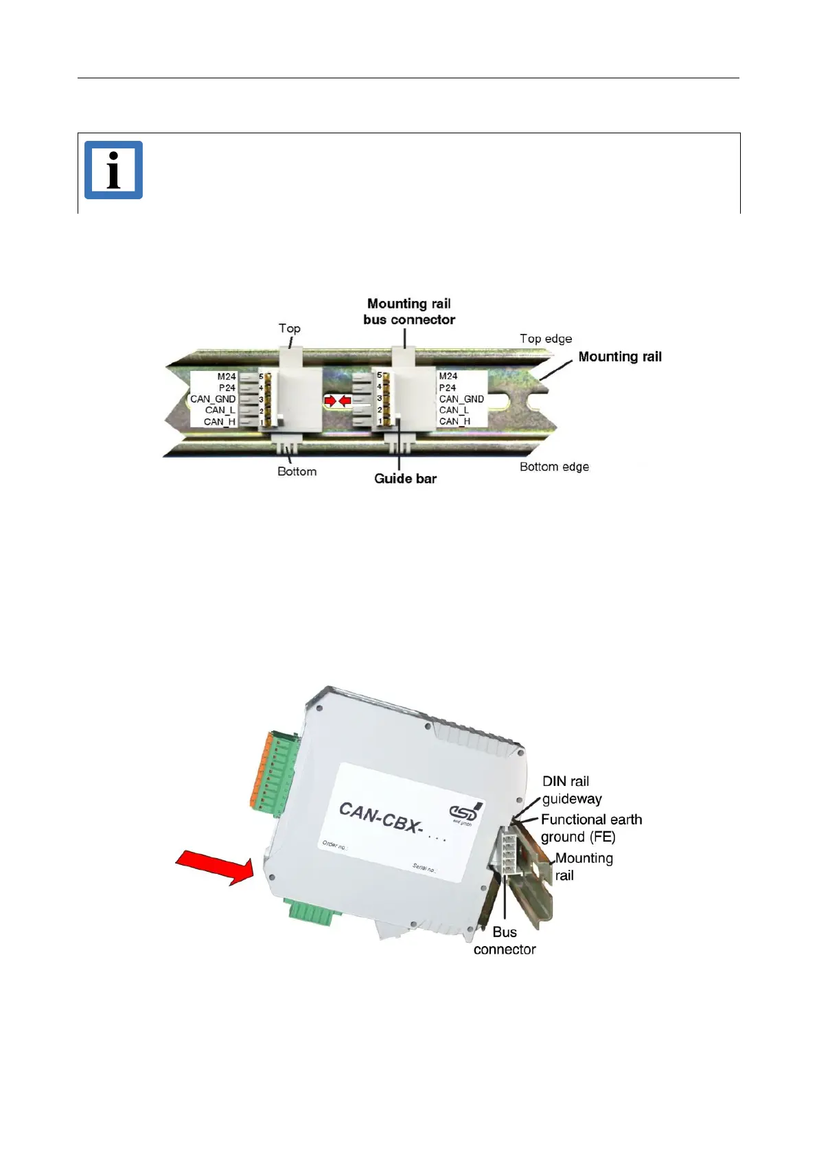
Figure. 12: Mounting rail with bus connector
1. Position the InRailBus connector on the mounting rail and snap it onto the mounting rail using
slight pressure. Plug the bus connectors together to contact the communication and power
signals (in parallel with one). The bus connectors can be plugged together before or after
mounting the CAN-CBX modules. The mounting rail bus connector is not included in the
amount of delivery and has to be ordered separately.
2. Place the CAN-CBX module with the DIN rail guideway on the top edge of the mounting rail.
Figure. 13: Mounting CAN-CBX modules
CAN-DP/2, CANopen-DP/2
Hardware Manual • Doc. No.: C.2907.21 / Rev. 1.1
Page 29 of 34