Appendix InRailBus (Option)
9.2.4 Connection of CAN
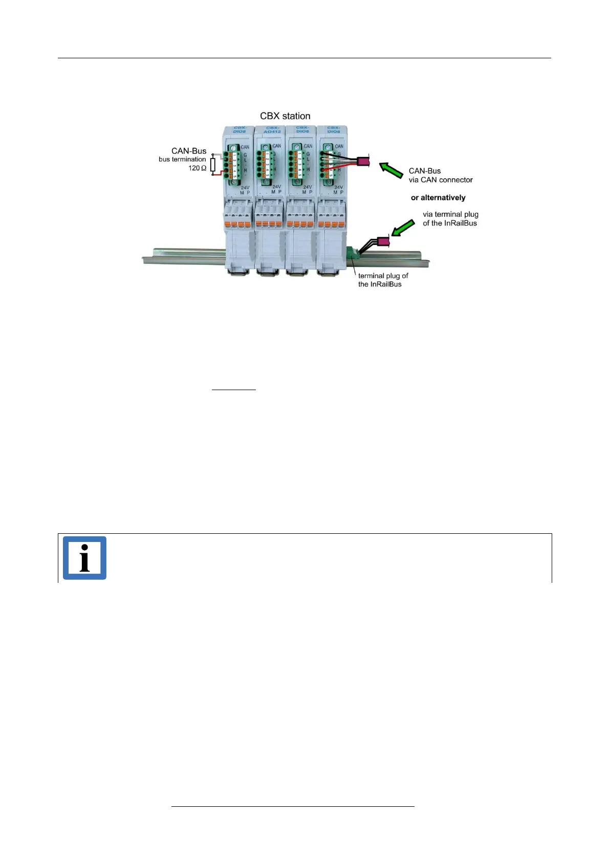
Figure. 17: Connecting the CAN signals to the CAN-CBX station
Generally the CAN signals can be fed via the CAN connector of the first CAN-CBX module of the
CBX station. The signals are then connected through the CAN-CBX station via the InRailBus. To
lead through the CAN signals the CAN bus connector of the last CAN-CBX module of the CAN-
CBX station has to be used. The CAN connectors of the CAN-CBX modules which are not at the
ends of the CAN-CBX station must not be connected to the CAN bus, because this would cause
incorrect branching.
A bus termination must be connected to the CAN connector of the CAN-CBX module at the end of
the CBX-InRailBus (see Fig. 17), if the CAN bus ends there.
9.3 Remove the CAN-CBX Module from InRailBus
If the CAN-CBX module is connected to the InRailBus please proceed as follows:
Release the module from the mounting rail in moving the foot catch (see Fig. 13) downwards (e.g.
with a screwdriver). Now the module is detached from the bottom edge of the mounting rail and
can be removed.
Note:
It is possible to remove individual devices from the whole without interrupting the
InRailBus connection, because the contact chain will not be interrupted.
Page 32 of 34
Hardware Manual • Doc. No.: C.2907.21 / Rev. 1.1
CAN-DP/2, CANopen-DP/2