Technical Data
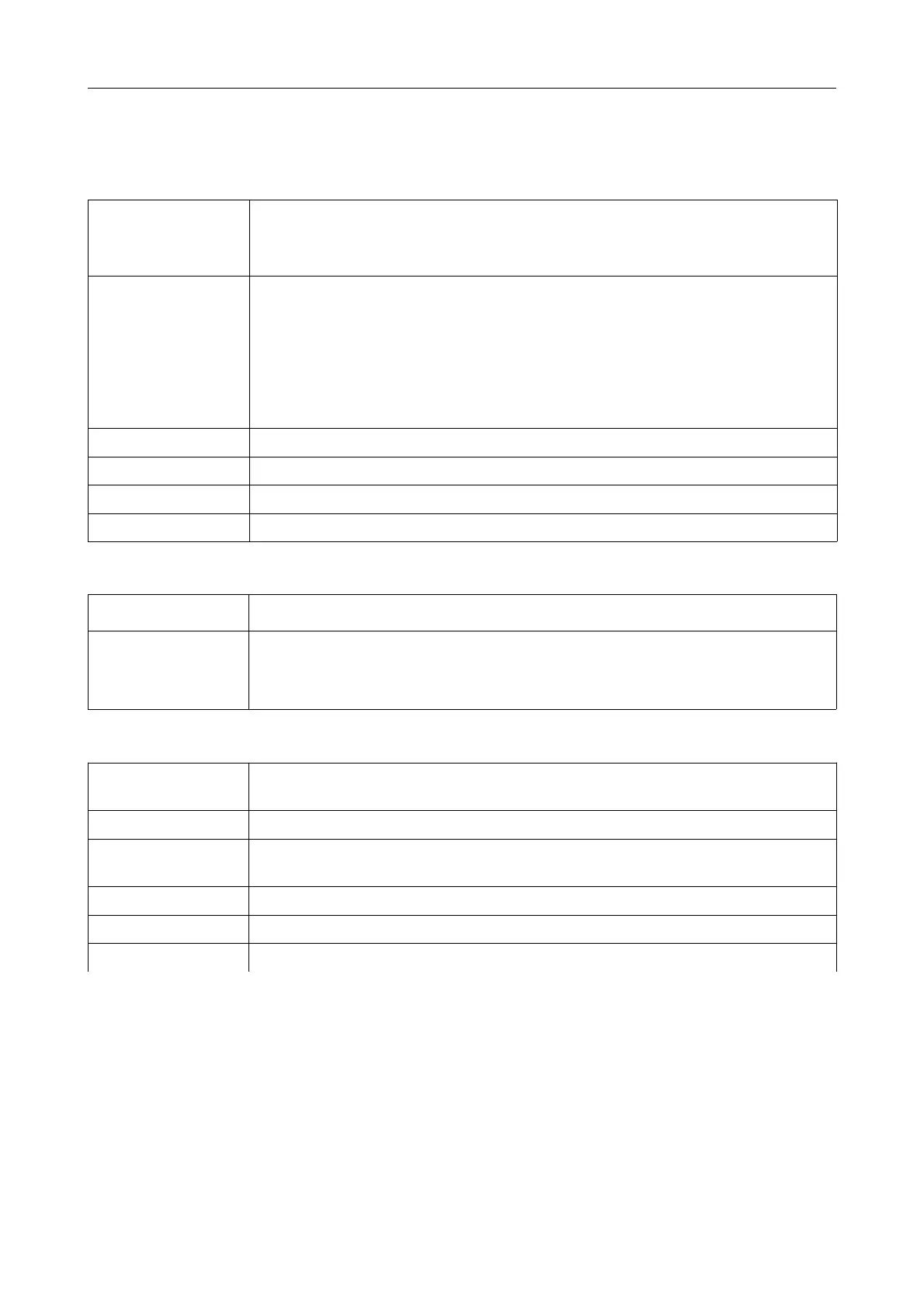
5. Technical Data
5.1 General Technical Data
Power supply
voltage
nominal voltage: 24 V/DC ± 20%
Current consumption
(24 V, 20 °C) typical: 40 mA
Connectors
CAN interface: 5-pin MINI COMBICON or InRail Bus
PROFIBUS-DP
inteface: 9-pin DSUB, female
Power supply: 4-pin COMBICON with spring-cage
connection or InRailBus
Service Interface: USB type B connector
Temperature range 0...55 °C ambient temperature
Humidity max. 90%, non-condensing
Dimensions 22.5 mm x 99 mm x 114.5 mm
Weight ca. 125 g
5.2 Microprocessor and Memory
CPU ARM
®
Cortex™-M3, STM2F205, 32-bit
Memory
SRAM: 512 KB x 16 bit (1MB)
Flash-EPROM: 256 KB, integrated in
microcontroller
Serial EEPROM 4 KB
5.3 CAN Interface
Number of CAN
interfaces
1 x CAN
CAN controller ISO11898-1 (CAN 2.0)
Physical Layer
Physical Layer according to ISO 11898-2, transmission rate programmable
from 10 Kbit/s to 1 Mbit/s
Electrical isolation via magnetic couplers and DC/DC converters
Bus termination terminating resistor has to be set externally, if required
Connector 5-pin MINI COMBICON with spring-cage connection
CAN-DP/2, CANopen-DP/2
Hardware Manual • Doc. No.: C.2907.21 / Rev. 1.1
Page 13 of 34