Overview
1. Overview
1.1 Module Description CAN-DP, CANopen-DP
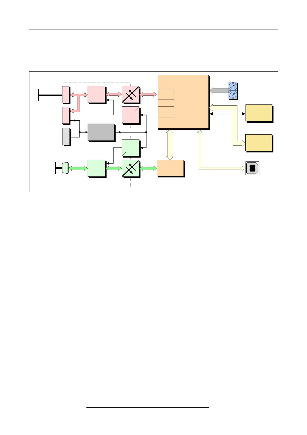
Fig. 1: Block-circuit diagram of the CAN-DP/2 module
By means of the CAN-DP/2 and CANopen-DP/2 modules, any PROFIBUS DP master can be
connected to a CAN network.
The CAN-DP/2 module (order no.: C.2907.02) is equipped with a VPC3+ DP-Slave controller and
acts like a slave I/O component on the DP-bus, with a total of up to 300 bytes input and output
data. Maximum 244 bytes of the total of 300 bytes can be used as input data (with 56 byte output
data) or maximum 244 bytes can be used as output data (with 56 bytes input data).
The CANopen-DP/2 module (order no.: C.2909.02) is equipped with a VPC3+ DP-Slave controller
and acts like a slave I/O component on the DP-bus with a maximum of 240 bytes input data and
maximum 240 bytes output data.
The CAN-DP/2 and CANopen-DP/2 modules operate internally with an ARM Cortex™-M3
processor, which buffers the CAN and PROFIBUS DP data into the local SRAM. The firmware and
configuration data are kept in the Flash. Parameters are stored by means of a serial EEPROM.
The ISO 11898-2-compliant CAN interface allows a maximum data-transfer rate of 1 Mbit/s. The
PROFIBUS DP slave interface automatically recognizes all usual bit rates up to 12 Mbit/s. The DP
interface as well as the CAN interface are electronically insulated by optocouplers and DC/DC
converters.
The CAN is connected by means of a 5-pin spring-cage connector in MINI COMBICON design.
According to standard, the DP interface is equipped with a 9-pin female DSUB connector.
The configuration of the CAN-DP/2 and CANopen-DP/2 is done via PROFIBUS
®
tool, e.g.
SIMATIC Manager.
Page 8 of 34
Hardware Manual • Doc. No.: C.2907.21 / Rev. 1.1
CAN-DP/2, CANopen-DP/2