Connector Assignments
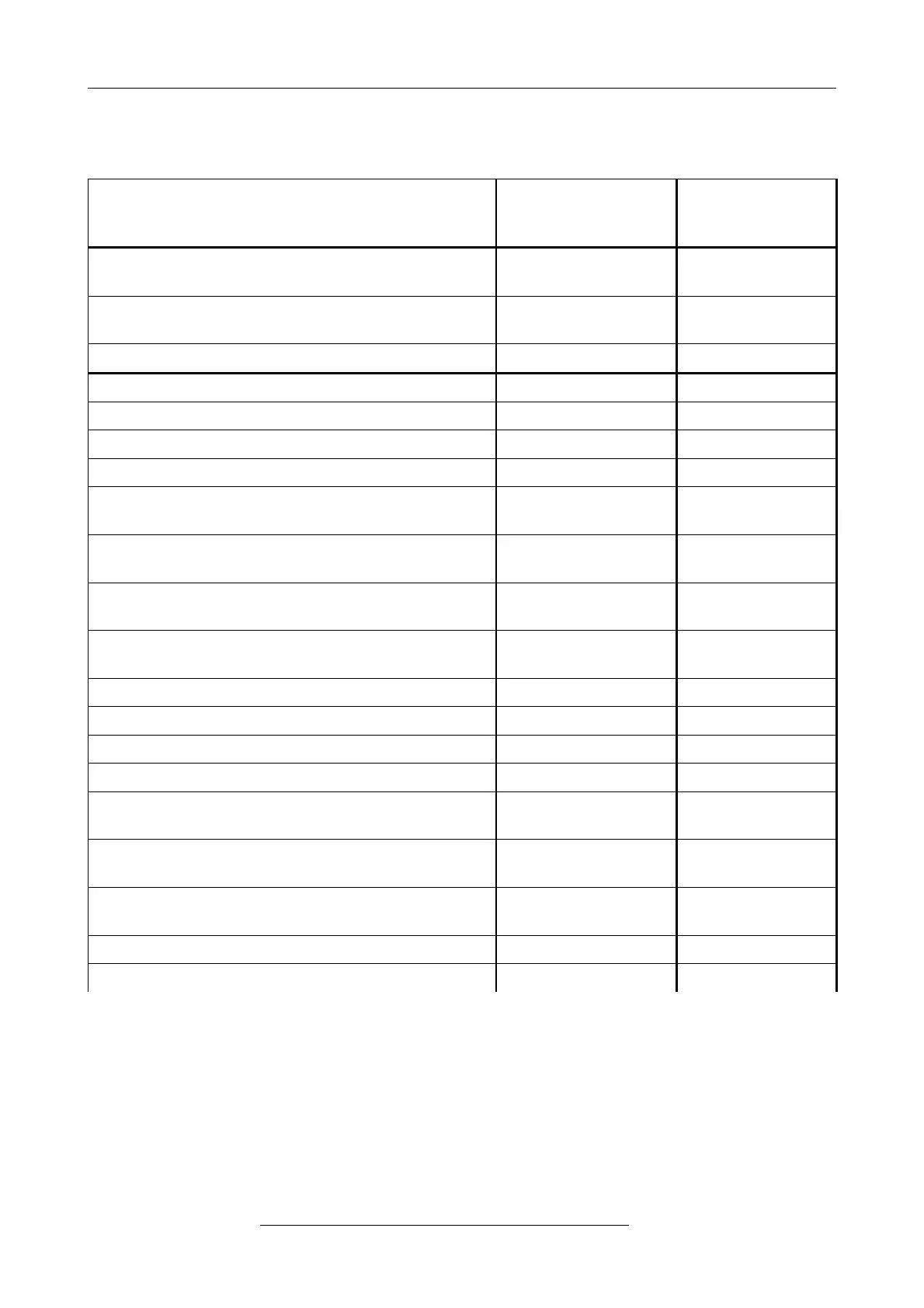
6.4 Conductor Connection/Conductor Cross Sections
The following table contains an extract of the technical data of the line connectors.
Interface
Power Supply
Voltage
24 V
CAN-Connector
Connector type plug component
(Range of articles)
FKCT 2,5/..-ST KMGY FK-MCP 1,5/5-
STF-3,81
Connection method spring-cage
connection
spring-cage
connection
Stripping length 10 mm 9 mm
Conductor cross section solid min. 0,2 mm² 0.14 mm²
Conductor cross section solid max. 2,5 mm² 1.5 mm²
Conductor cross section stranded min. 0,2 mm² 0,14 mm²
Conductor cross section stranded max. 2,5 mm² 1,5 mm²
Conductor cross section stranded, with ferrule
without plastic sleeve min.
0,25 mm² 0,25 mm²
Conductor cross section stranded, with ferrule
without plastic sleeve max.
2,5 mm² 1,5 mm²
Conductor cross section stranded, with ferrule with
plastic sleeve min.
0,25 mm² 0,25 mm²
Conductor cross section stranded, with ferrule with
plastic sleeve max.
2, 5 mm² 0,5 mm²
Conductor cross section AWG/kcmil min. 24 26
Conductor cross section AWG/kcmil max 12 16
2 conductors, solid not allowed not allowed
2 conductors, stranded not allowed not allowed
2 conductors, stranded, ferrules without plastic
sleeve
not allowed not allowed
2 conductors with same cross section, stranded,
TWIN ferrules with plastic sleeve, min.
0,5 mm² not allowed
2 conductors with same cross section, stranded,
TWIN ferrules with plastic sleeve, max.
1,5 mm² not allowed
Minimum AWG according to UL/cUL 26 28
Maximum AWG according to UL/cUL 12 16
Page 18 of 34
Hardware Manual • Doc. No.: C.2907.21 / Rev. 1.1
CAN-DP/2, CANopen-DP/2