Appendix InRailBus (Option)
3. Swivel the CAN-CBX module onto the mounting rail in pressing the module downwards
according to the arrow as shown in figure 13. The housing is mechanically guided by the DIN
rail bus connector.
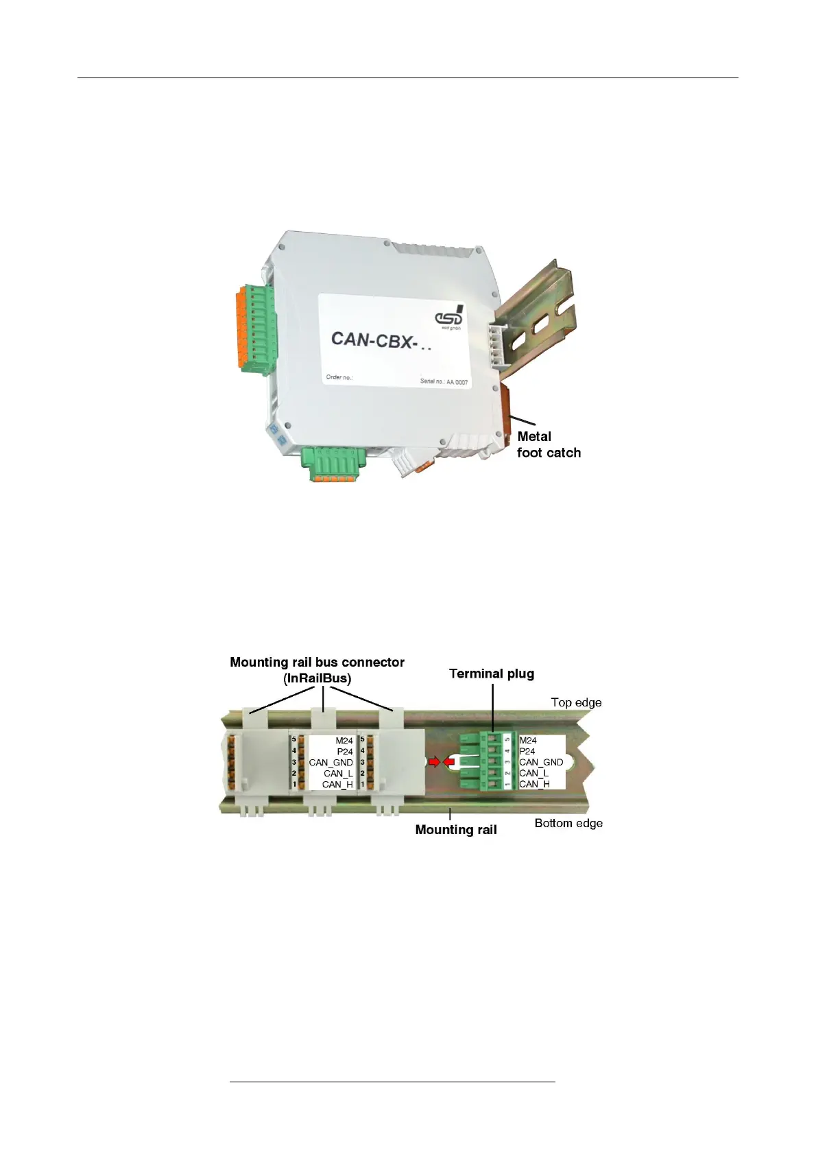
4. When mounting the CAN-CBX module the metal foot catch snaps on the bottom edge of the
mounting rail. Now the module is mounted on the mounting rail and connected to the InRailBus
via the bus connector. Connect the bus connectors and the InRailBus, if not already done.
Figure. 14: Mounted CAN-CBX module
9.2.2 Connecting Power Supply and CAN Signals to CBX-InRailBus
To connect the power supply and the CAN-signals via the InRailBus, a terminal plug is needed.
The terminal plug is not included in delivery and must be ordered separately (order no.: C.3000.02,
see order information for InRailBus Accessories, page 34).
Figure. 15: Mounting rail with InRailBus and terminal plug
Plug the terminal plug into the socket on the right of the mounting-rail bus connector of the
InRailBus, as described in Figure 15. Then connect the CAN interface and the power supply
voltage via the terminal plug.
Page 30 of 34
Hardware Manual • Doc. No.: C.2907.21 / Rev. 1.1
CAN-DP/2, CANopen-DP/2