CAN Troubleshooting Guide
8.2 Electrical Grounding
The CAN_GND of the CAN network has to be connected to the functional earth potential (FE) at
only one point. This test will indicate if the CAN_GND is grounded in several places.
To test it, please
1.
2.
3.
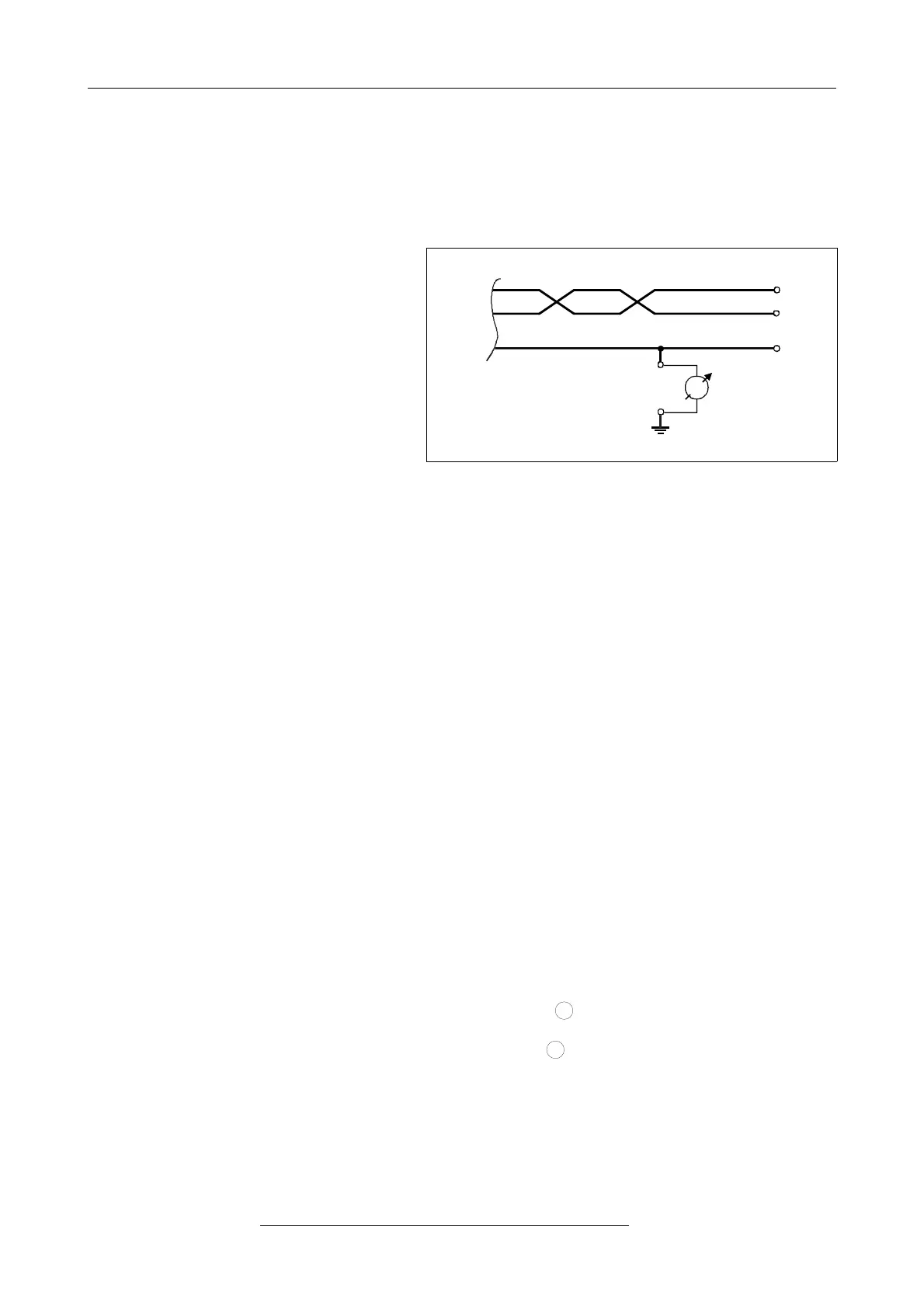
Disconnect the CAN_GND from the
earth potential (FE).
Measure the DC resistance
between CAN_GND and earth
potential (see figure on the right).
Connect CAN_GND to earth potential.
Figure. 10: Simplified schematic diagram of ground test measurement
The resistance should be higher than 1 MΩ. If it is lower, please search for additional grounding of
the CAN_GND wires.
8.3 Short Circuit in CAN Wiring
A CAN bus might possibly still be able to transmit data if there is a short circuit between CAN_GND
and CAN_L, but the error rate will increase strongly. Make sure that there is no short circuit
between CAN_GND and CAN_L!
8.4 CAN_H/CAN_L-Voltage
Each node contains a CAN transceiver that outputs differential signals. When the network
communication is idle the CAN_H and CAN_L voltages are approximately 2.5 volts. Faulty
transceivers can cause the idle voltages to vary and disrupt network communication.
To test for faulty transceivers, please
1. Turn on all supplies.
2. Stop all network communication.
3. Measure the DC voltage between CAN_H and GND
(see figure above).
4. Measure the DC voltage between CAN_L and GND
(see figure above).
Page 26 of 34
Hardware Manual • Doc. No.: C.2907.21 / Rev. 1.1
CAN-DP/2, CANopen-DP/2