Hardware Installation
3. Hardware Installation
To put the CAN-DP/2, CANopen-DP/2 into operation, please follow the installation notes.
Step Procedure
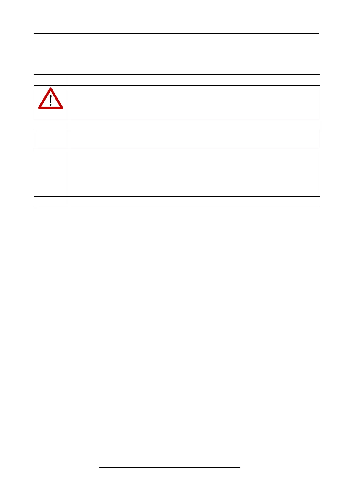
Read the safety instructions at the beginning of this document carefully, before
you start with the hardware installation!
1. Check the position of the coding switches.
2. Mount the CAN-DP/2, CANopen-DP/2 module and connect the interfaces (CAN,
PROFIBUS-DP, power supply voltage).
3. Please note that the CAN bus has to be terminated at both ends! esd offers special T-
connectors and termination connectors. Additionally the CAN_GND signal has to be
connected to earth at exactly one point in the CAN network. Therefore the CAN
termination connectors offered by esd have got a grounding contact.
A CAN participant with a CAN interface which is not electrically isolated corresponds
to the grounding of the CAN-GND.
4. Switch on the 24 V-power supply voltage of the CAN-DP/CANopen-DP.
Page 10 of 34
Hardware Manual • Doc. No.: C.2907.21 / Rev. 1.1
CAN-DP/2, CANopen-DP/2