Table of Contents
Safety Instructions...........................................................................................................................5
1. Overview......................................................................................................................................9
2. Hardware-Installation..................................................................................................................10
2.1 Connections.........................................................................................................................10
2.2 LED-Assignment..................................................................................................................11
3. Starting Up.................................................................................................................................13
4. Technical Data...........................................................................................................................14
4.1 General Technical Data.......................................................................................................14
4.2 Microcontroller.....................................................................................................................14
4.3 CAN Interface......................................................................................................................15
4.4 PROFINET IO Interface.......................................................................................................15
4.5 DIAG, Serial Interface via USB-Interface.............................................................................15
5. Interfaces and Connector Assignments......................................................................................16
5.1 24V-Power Supply Voltage..................................................................................................16
5.2 CAN..................................................................................................................................... 17
5.3 24V and CAN via InRailBus ................................................................................................18
5.4 Conductor Connection/Conductor Cross Sections...............................................................18
5.5 PORT1, PORT2 - PROFINET IO.........................................................................................19
5.6 DIAG.................................................................................................................................... 20
5.6.1 Default Settings of CAN-PN........................................................................................20
5.6.2 Connector Assignment................................................................................................20
6. Correct Wiring of Electrically Isolated CAN Networks.................................................................21
6.1 Standards concerning CAN Wiring......................................................................................21
6.2 Light Industrial Environment (Single Twisted Pair Cable).....................................................22
6.2.1 General Rules.............................................................................................................22
6.2.2 Cabling........................................................................................................................23
6.2.3 Branching....................................................................................................................23
6.2.4 Termination.................................................................................................................23
6.3 Heavy Industrial Environment (Double Twisted Pair Cable).................................................24
6.3.1 General Rules.............................................................................................................24
6.3.2 Device Cabling............................................................................................................25
6.3.3 Branching....................................................................................................................25
6.3.4 Termination.................................................................................................................25
6.4 Electrical Grounding.............................................................................................................26
6.5 Bus Length...........................................................................................................................26
6.6 Examples for CAN Cables...................................................................................................27
6.6.1 Cable for light industrial Environment Applications (Two-Wire)...................................27
6.6.2 Cable for heavy industrial Environment Applications (Four-Wire)................................27
7. CAN Troubleshooting Guide.......................................................................................................28
7.1 Termination..........................................................................................................................28
7.2 Electrical Grounding.............................................................................................................29
7.3 Short Circuit in CAN Wiring..................................................................................................29
7.4 CAN_H/CAN_L-Voltage ......................................................................................................29
7.5 CAN Transceiver Resistance Test.......................................................................................30
7.6 Support by esd.....................................................................................................................30
8. Appendix InRailBus (Option)......................................................................................................31
8.1 Connector Assignment ........................................................................................................31
8.2 Using InRailBus (Option).....................................................................................................32
8.3 Installation of the Module Using InRailBus-Connector.........................................................32
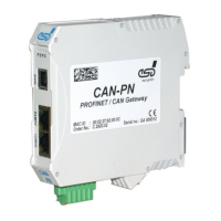
CAN-PN
Hardware Manual • Doc. No.: C.2920.21 / Rev. 1.4
Page 7 of 38