Interfaces and Connector Assignments
5.2 CAN
The CAN interface can be connected via CAN connector (X2) or optional via InRailBus.
Use the mounting-rail bus connector of the CBX-InRailBus for the connection via the InRailBus,
see order information in the appendix (page 38).
Device connector: Phoenix Contact MC 1,5/5-GF-3,81
Line connector: Phoenix Contact FK-MCP 1,5/5-STF-3,81, spring-cage connection
(included in delivery)
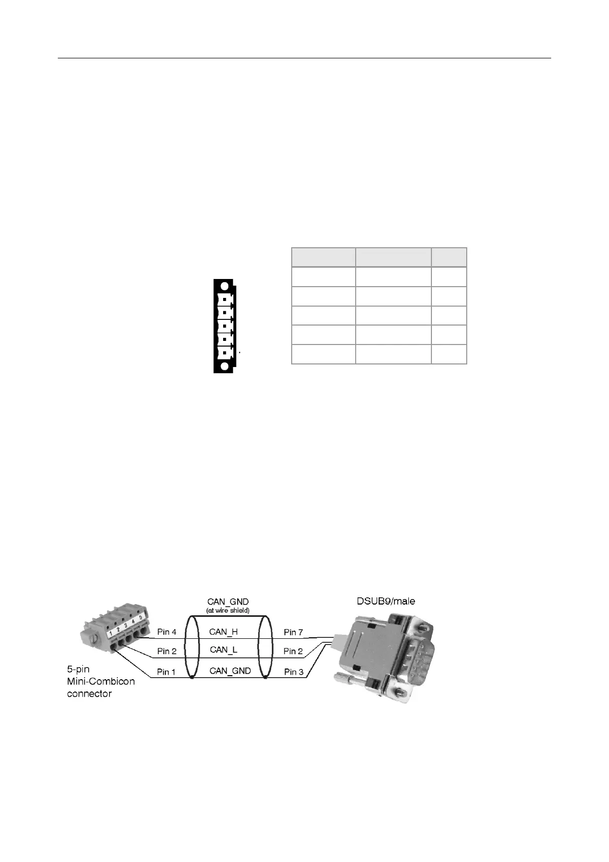
Pin Position: Pin Assignment:
(Illustration of device
connector)
Aufdruck Signal Pin
G CAN_GND 1
L CAN_L 2
Sh Shield 3
H CAN_H 4
• - 5
Signal Description:
CAN_L, CAN_H ... CAN signals
CAN_GND ... reference potential of the local CAN physical layer
Shield ... pin for line shield connection (using hat rail mounting direct contact to the
mounting rail potential)
- ... not connected
Recommendation of an adapter cable from 5-pin COMBICON (here line connector
FK-MCP1,5/5-STF_3,81 with spring-cage-connection) to 9-pin DSUB:
The assignment of the
9-pin DSUB-connector
and the 5-pin Mini-
COMBICON is designed
according to CiA 303
Part 1.
CAN-PN
Hardware Manual • Doc. No.: C.2920.21 / Rev. 1.4
Page 17 of 38