8
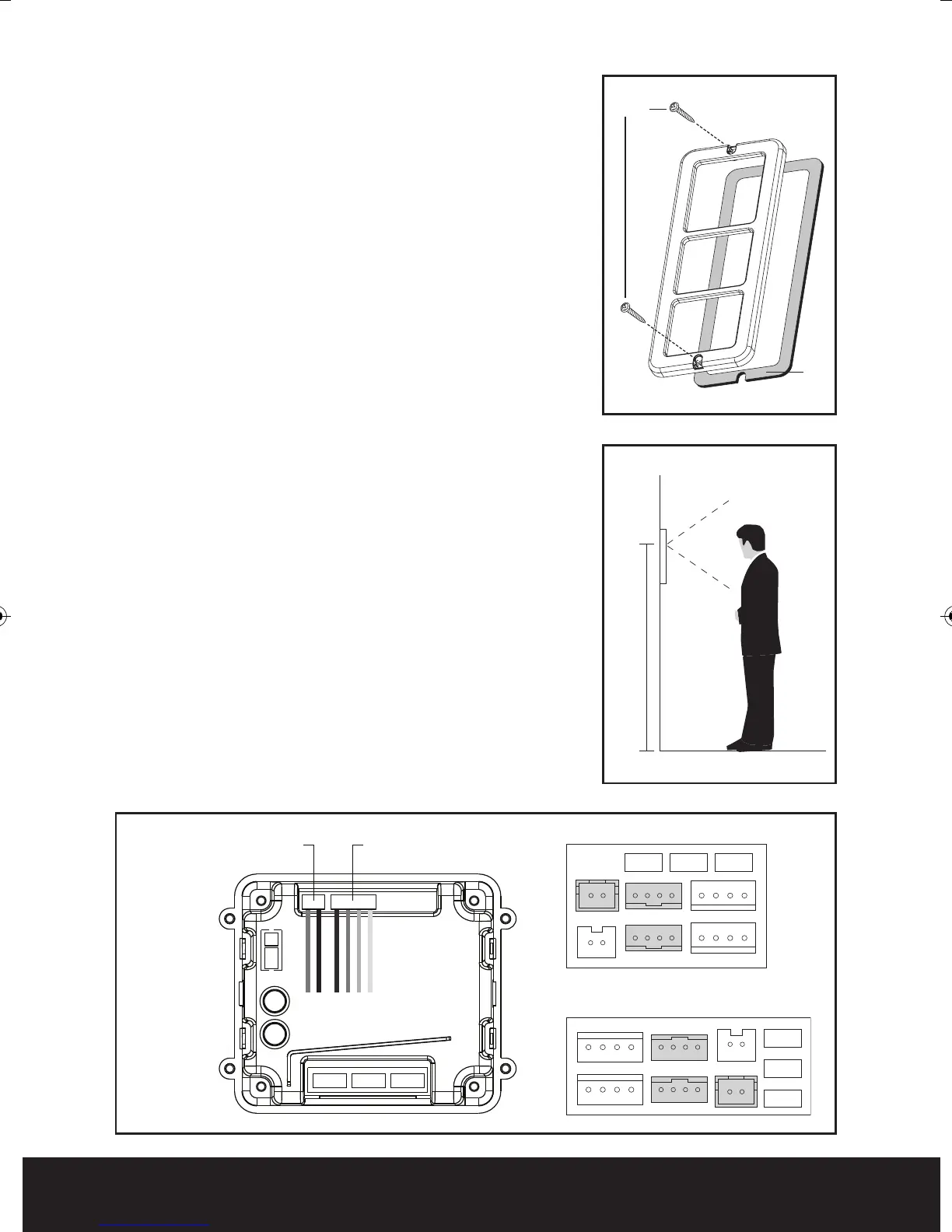
Fig. 5
Fig. 6
CN2
J2 J3 J1
POWER
CN1-2
CN1
CN4
CN3
CN1
J2
J1
J3
CN2
CN6
CN3
CN4
Fig. 7
Seal
1.45m
Screws
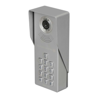
Assembly of the external call station
Once all connections have been made and all plugs
inserted into the appropriate sockets fit the rubber
seal to the cover of the call station see Fig. 5. Use
the two supplied screws to secure the front cover to
the back plate, paying attention to the seal so it
remains seated correctly
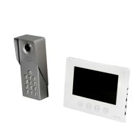
Fitting and wiring the handset
On all types of handsets fitted to a MX system
please remove the jumper labelled J3. This can be
found next to the connecting plugs on the rear.
Locate the metal back plate and observe the arrow
and the word up see Fig. 1 item 1.
Fit mounting plate to the selected location,
recommended mounting height 1.45m see Fig. 6.
Feed the cable from the local transformer and the
external call button though the center opening see
Fig. 8 item 1.
Connect the corres
ponding cores from the external
call button cable to the brown plug (supplied)
consisting of red, blue, yellow and white cores.
Once connected, fit the brown plug into the rear of
the handset socket CN1 for call station one and CN2
for call station two see Fig. 7.
Connect the corresponding cores from the
transformer to the white plug (supplied) consisting
of red and black cores.
Once connected, fit the
white plug into the rear of
the handset socket marked 5 (+) and 6 (-) see Fig. 7.
White
Plug
White
Interconnecting
Plug
Rear of
Outdoor Panel
Rear of the standard handset
Rear of hands free (HF) handset
Enterview MX Manual_Layout 2 07/10/2013 14:59 Page 8