MAGPRO16 Addressable Fire Alarm Panel – Installation and Programming Manual
12
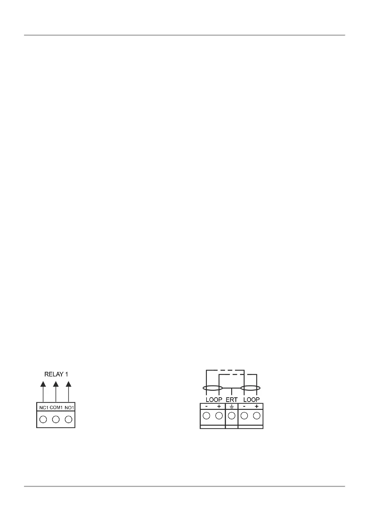
Description of the terminal row (left to right):
RELAY 1 - 4 – Programmable volt free change over relay contacts each, 24VDC@15A. Each relay has one
NO (normal open) and one NC (normal closed) contact with common lead on a terminal. When a relay output
is activated the NO contact is closed and the NC contact is opened.
FAULT – Potential, monitored output for connection of auxiliary devices, 24 VDC/ 0.3А. This output is
deactivated in case of system trouble or fault.
EXT - Potential, monitored output for fire extinguishing, 24 VDC/ 0.3А. This output is activated in case of a fire
alarm condition.
FIRE – Potential, monitored output for connection of auxiliary devices (signaling devices for example), 24 VDC/
0.3А. This output is activated in case of fire in the premises.
AUX – Potential output for power supply of auxiliary devices, 24 VDC/ 0.5А.
SND 1, SND 2 – Potential, monitored outputs for connecting sounders, 24 VDC/ 0.5А.
IN PC (Input Protection Alarm Confirmation) – Input for monitoring of signal „Confirmation for extinguishing
started in the site“ sent by extinguishing control panel.
IN FP (Input Fault Protection Panel) – Input for monitoring of signal „Fault“ sent by extinguishing control panel.
IN AmC (Input Alarm Confirmation) – Input for monitoring of signal „Alarm confirmation“ sent by extinguishing
control panel.
LOOP 1 (-LOOP+ / +ERT / -LOOP+) – Terminal row for connecting Loop 1 in the system.
LOOP 2 – Interface connector for adding MAGPRO16-L250 loop (for Loop 2) in the system configuration.
INDICATION – Interface connection for the indication module.
POWER – Interface connection for the main power supply unit.
JP7 – Jumper for enable/ disable the built-in battery for supporting the real time clock in case of main and
backup power supply failure.
PRINTER - RS232 interface connector for heat-printer.
USB UTG – Micro USB A/B connector for firmware update of the main microprocessor via PC or USB flash
drive; suitable also for programming via MAGPRO programming software.
BATT – Connector with wires (red and black) for connection to the accumulator battery. The type of connection
is according the battery terminals – to every cable shoe is added a separate cable lug connector Ø5mm (M5).
Restore Defaults – Jumper for full hardware reset of the panel and restoring the factory default settings.
Earth Fault – Jumper for enable/disable indication for earth fault.
Example: If you want to enable the earth fault indication set a jumper on Earth Fault terminals.
NET – Interface connector for a redundant network module to the system configuration.
Ajax – Interface connector for adding of AJAX LAN communication module to the system configuration.
Fuses:
AUX – 0.5А, PTC type, resettable
FAULT, EXT, FIRE – 0.3A, PTC type, resettable
BATT – 7A, PTC type, resettable
LED indication:
LED 1 (red) – Indication for scanning the devices connected to Loop1. In normal operation mode the LED
lights on continuously in 10 seconds intervals.
LED 2 (green) – Indication for data transfer between the main microprocessor of the panel and the controller
for Loop 1.In normal operation mode is constantly blinking.
Temperature sensor:
The temperature sensor is used for measurement of the battery temperature. The sensor is mounted at the end of the
wires couple factory connected to “Temperature sensor” terminal on the panel’s PCB.
The temperature sensor should be places behind or under the accumulator battery.
Figure 8 – Internal structure
of relay output
Figure 9 – Connection to the
loop controller