MAGPRO16 Addressable Fire Alarm Panel – Installation and Programming Manual
17
2.6. Connecting a Heat Printer
The addressable fire alarm panel MAGPRO16 is equipped with RS232
interface connector, situated in the middle of the main PCB, for
connecting a heat printer. The heat printer allows the technician to print
the log file for the alarm and fault events, warnings and changes during
programming. The capacity of log file is 10 240 events, which are
saved with date and time of occurring – see also item 7.1.4.
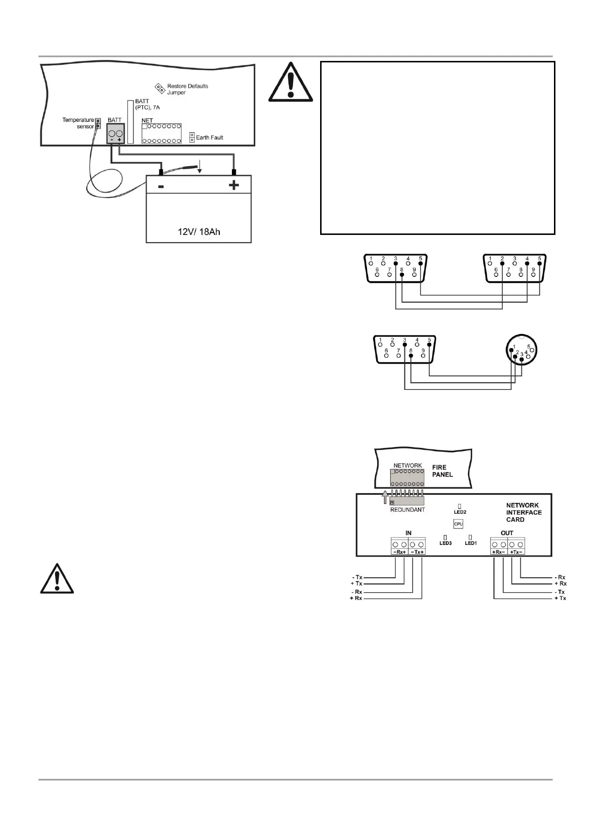
The addressable fire alarm panel MAGPRO16 supports Canon 9 type
external printers, models Kafka and Datecs. For connecting the
MAGPRO16 panel to the heat printer you have to prepare a special
cable for the purpose – connect two male DB9-DB9 (Datecs printer) or
DB9-DIN5 (Kafka printer) type connectors as shown on Figure 18.
Before printing (access levels 2 and 3) make sure that the heat printer
is connected to the ‘PRINTER’ interface connector on the main PCB
and the printer is powered on.
2.7. Connecting a Network Interface Card (MAGPRO-NIC)
The addressable fire alarm panel MAGPRO16 is designed with option
for connection in a Ethernet network with other MAGPRO16 or
MAGPRO96 addressable panels (up to 32). The network interface
card is mounted under the main PCB and is connected to ‘NET’
connector – Figure 19. The card should be fixed with screws to the
metal bottom. The maximum cable length between two network
interface cards is 1000m.
Attention: NEVER add or remove the network interface
card to the fire panel configuration WHEN THE MAIN
AND BACKUP POWER SUPPLIES ARE ON!
2.8. Connecting an AJAX LAN Communication Module
The addressable fire alarm panel MAGPRO16 is designed for monitoring via serial interface connection using
specialized AJAX communication module. The monitoring could be realized over LAN network, according the type of
the used module. The communication module is mounted on the place under the second loop controller and it is fixed
with suitable screws to the metal bottom. The connection is realized with interface flat cable between the ‘AJAX’
connector on the main PCB and the interface connector on the communication module itself.
Attention: NEVER add or remove the communication module to the fire panel configuration WHEN THE MAIN
AND BACKUP POWER SUPPLIES ARE ON!
Attention: The connection between the
accumulator battery and the main power
source has some special features.
It is strongly recommended to use only
battery with electrical characteristics and
dimensions pointed from the manufacturer.
Before connecting to the power source
check the polarity of the battery. Connect the
battery after the mains supply is turned on.
If the battery is new it will take a few hours
before its complete charging!
Figure 17. Connecting
the accumulator battery
Attention: The connection between the
accumulator battery and the main power
source has some special features.
It is strongly recommended to use only battery
with electrical characteristics and dimensions
pointed from the manufacturer.
Before connecting to the power source check
the polarity of the battery. Connect the battery
after the mains supply is turned on.
If the battery is new it will take a few hours
before its complete charging!
To measure the current temperature of the
battery, place the temperature sensor behind
or under the battery.