MAGPRO16 Addressable Fire Alarm Panel – Installation and Programming Manual
11
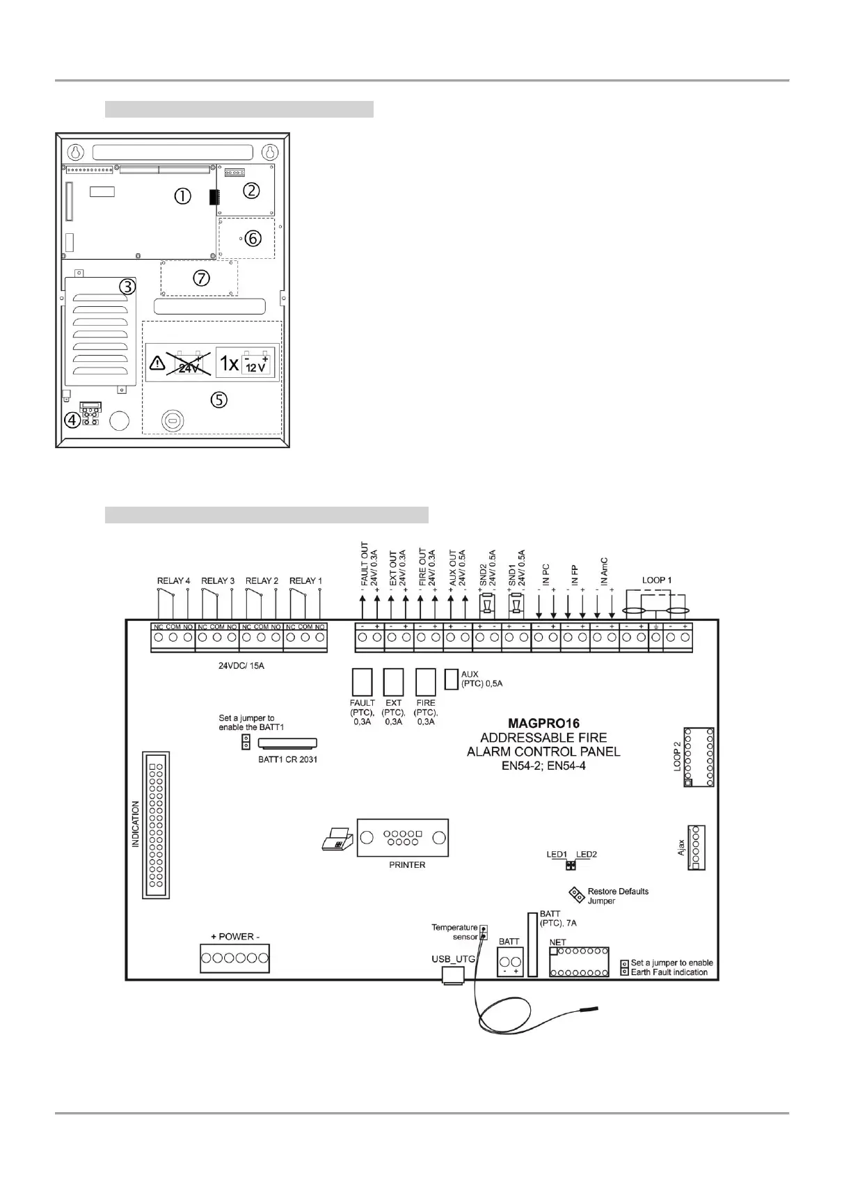
2.2.2 Configuration of the basic modules
Figure 6 – Configuration of the modules in the box:
1 – Main PCB (control panel)
2 – Second loop controller (optional, it may not be present in your
system configuration)
3 – Power supply unit
4 – Terminal 230V for connection of the main power supply cable
5 – Place for accumulator battery, 1 х 12V/ 18Ah
6 – Place for mounting of AJAX LAN communication module
7 – Place for mounting of redundant network module
2.2.3 Description of the main PCB (control panel)
Figure 7 – Main PCB of the MAGPRO16 fire alarm panel